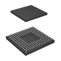
DF2552BR26DV Renesas Electronics America, DF2552BR26DV Datasheet - Page 28

DF2552BR26DV
Manufacturer Part Number
DF2552BR26DV
Description
IC H8S/2552 MCU FLASH 176-LFBGA
Manufacturer
Renesas Electronics America
Series
H8® H8S/2500r
Specifications of DF2552BR26DV
Core Processor
H8S/2000
Core Size
16-Bit
Speed
26MHz
Connectivity
I²C, SCI
Peripherals
POR, PWM, WDT
Number Of I /o
104
Program Memory Size
512KB (512K x 8)
Program Memory Type
FLASH
Ram Size
32K x 8
Voltage - Supply (vcc/vdd)
3 V ~ 5.5 V
Data Converters
A/D 16x10b; D/A 2x8b
Oscillator Type
Internal
Operating Temperature
-40°C ~ 85°C
Package / Case
176-LFBGA
Lead Free Status / RoHS Status
Lead free / RoHS Compliant
Eeprom Size
-
Available stocks
Company
Part Number
Manufacturer
Quantity
Price
Company:
Part Number:
DF2552BR26DV
Manufacturer:
Renesas Electronics America
Quantity:
10 000
- Current page: 28 of 980
- Download datasheet (6Mb)
22.5 Hardware Standby Mode ................................................................................................... 804
22.6 Module Stop Mode ............................................................................................................ 805
22.7 Watch Mode....................................................................................................................... 806
22.8 φ Clock Output Disabled Function .................................................................................... 807
22.9 Usage Notes ....................................................................................................................... 808
Section 23 List of Registers................................................................................. 811
23.1 Register Addresses (in address order)................................................................................ 812
23.2 Register Bits....................................................................................................................... 832
23.3 Register States in Each Operating Mode ........................................................................... 853
Section 24 Electrical Characteristics ................................................................... 871
24.1 Power Supply Voltage and Operating Frequency Range................................................... 871
24.2 Absolute Maximum Ratings .............................................................................................. 873
24.3 DC Characteristics ............................................................................................................. 874
24.4 AC Characteristics ............................................................................................................. 882
24.5 A/D Conversion Characteristics ........................................................................................ 903
24.6 D/A Conversion Characteristics ........................................................................................ 904
24.7 Flash Memory Characteristics ........................................................................................... 905
Appendix
A.
B.
Rev. 6.00 Sep. 24, 2009 Page xxvi of xlvi
REJ09B0099-0600
22.4.4 Software Standby Mode Application Example..................................................... 802
22.5.1 Transition to Hardware Standby Mode................................................................. 804
22.5.2 Clearing Hardware Standby Mode........................................................................ 804
22.5.3 Hardware Standby Mode Timing.......................................................................... 804
22.7.1 Transition to Watch Mode .................................................................................... 806
22.7.2 Clearing Watch Mode........................................................................................... 806
22.9.1 I/O Port Status....................................................................................................... 808
22.9.2 Current Consumption during Oscillation Settling Wait Period ............................ 808
22.9.3 DTC Module Stop................................................................................................. 808
22.9.4 On-Chip Peripheral Module Interrupt................................................................... 808
22.9.5 Writing to MSTPCR ............................................................................................. 808
22.9.6 Entering Watch Mode and DTC Module Stop...................................................... 809
24.4.1 Power-On/Off Timing........................................................................................... 882
24.4.2 Clock Timing ........................................................................................................ 884
24.4.3 Control Signal Timing .......................................................................................... 886
24.4.4 Bus Timing ........................................................................................................... 889
24.4.5 Timing of On-Chip Peripheral Modules ............................................................... 895
I/O Port States in Each Pin State........................................................................................ 907
Product Codes .................................................................................................................... 911
......................................................................................................... 907
Related parts for DF2552BR26DV
Image
Part Number
Description
Manufacturer
Datasheet
Request
R

Part Number:
Description:
KIT STARTER FOR M16C/29
Manufacturer:
Renesas Electronics America
Datasheet:

Part Number:
Description:
KIT STARTER FOR R8C/2D
Manufacturer:
Renesas Electronics America
Datasheet:

Part Number:
Description:
R0K33062P STARTER KIT
Manufacturer:
Renesas Electronics America
Datasheet:

Part Number:
Description:
KIT STARTER FOR R8C/23 E8A
Manufacturer:
Renesas Electronics America
Datasheet:

Part Number:
Description:
KIT STARTER FOR R8C/25
Manufacturer:
Renesas Electronics America
Datasheet:

Part Number:
Description:
KIT STARTER H8S2456 SHARPE DSPLY
Manufacturer:
Renesas Electronics America
Datasheet:

Part Number:
Description:
KIT STARTER FOR R8C38C
Manufacturer:
Renesas Electronics America
Datasheet:

Part Number:
Description:
KIT STARTER FOR R8C35C
Manufacturer:
Renesas Electronics America
Datasheet:

Part Number:
Description:
KIT STARTER FOR R8CL3AC+LCD APPS
Manufacturer:
Renesas Electronics America
Datasheet:

Part Number:
Description:
KIT STARTER FOR RX610
Manufacturer:
Renesas Electronics America
Datasheet:

Part Number:
Description:
KIT STARTER FOR R32C/118
Manufacturer:
Renesas Electronics America
Datasheet:

Part Number:
Description:
KIT DEV RSK-R8C/26-29
Manufacturer:
Renesas Electronics America
Datasheet:

Part Number:
Description:
KIT STARTER FOR SH7124
Manufacturer:
Renesas Electronics America
Datasheet:

Part Number:
Description:
KIT STARTER FOR H8SX/1622
Manufacturer:
Renesas Electronics America
Datasheet:

Part Number:
Description:
KIT DEV FOR SH7203
Manufacturer:
Renesas Electronics America
Datasheet:


