DF2552BR26DV Renesas Electronics America, DF2552BR26DV Datasheet - Page 169
DF2552BR26DV
Manufacturer Part Number
DF2552BR26DV
Description
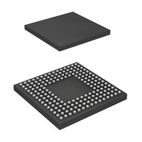
IC H8S/2552 MCU FLASH 176-LFBGA
Manufacturer
Renesas Electronics America
Series
H8® H8S/2500r
Specifications of DF2552BR26DV
Core Processor
H8S/2000
Core Size
16-Bit
Speed
26MHz
Connectivity
I²C, SCI
Peripherals
POR, PWM, WDT
Number Of I /o
104
Program Memory Size
512KB (512K x 8)
Program Memory Type
FLASH
Ram Size
32K x 8
Voltage - Supply (vcc/vdd)
3 V ~ 5.5 V
Data Converters
A/D 16x10b; D/A 2x8b
Oscillator Type
Internal
Operating Temperature
-40°C ~ 85°C
Package / Case
176-LFBGA
Lead Free Status / RoHS Status
Lead free / RoHS Compliant
Eeprom Size
-
Available stocks
Company
Part Number
Manufacturer
Quantity
Price
Company:

Part Number:
DF2552BR26DV
Manufacturer:
Renesas Electronics America
Quantity:
10 000


6.4
6.4.1
PBC operation can be disabled or enabled using the module stop control register. The initial
setting is for PBC operation to be halted. Register access is enabled by clearing module stop
mode. For details, see section 22, Power-Down Modes.
6.4.2
The PC break interrupt is shared by channels A and B. The channel from which the request was
issued must be determined by the interrupt handler.
6.4.3
The CMFA and CMFB flags are not automatically cleared to 0, so 0 must be written to CMFA or
CMFB after first reading the flag while it is set to 1. If the flag is left set to 1, another interrupt
will be requested after interrupt handling ends.
6.4.4
A PC break interrupt generated when the DTC is the bus master is accepted after the bus
mastership has been transferred to the CPU by the bus controller.
6.4.5
Even if the instruction at the address following a BSR, JSR, JMP, TRAPA, RTE, or RTS
instruction is fetched, it is not executed, and so a PC break interrupt is not generated by the
instruction fetch at the next address.
6.4.6
When the I bit is set by an LDC, ANDC, ORC, or XORC instruction, a PC break interrupt
becomes valid two states after the end of the executing instruction. If a PC break interrupt is set
for the instruction following one of these instructions, since interrupts, including NMI, are
disabled for a 3-state period in the case of LDC, ANDC, ORC, and XOR, the next instruction is
always executed. For details, see section 5, Interrupt Controller.
Usage Notes
Module Stop Mode Setting
PC Break Interrupts
CMFA and CMFB
PC Break Interrupt when DTC Is Bus Master
PC Break Set for Instruction Fetch at Address Following BSR, JSR, JMP, TRAPA,
RTE, or RTS Instruction
I Bit Set by LDC, ANDC, ORC, or XORC Instruction
Rev. 6.00 Sep. 24, 2009 Page 121 of 928
Section 6 PC Break Controller (PBC)
REJ09B0099-0600
Related parts for DF2552BR26DV
Image
Part Number
Description
Manufacturer
Datasheet
Request
R

Part Number:
Description:
KIT STARTER FOR M16C/29
Manufacturer:
Renesas Electronics America
Datasheet:

Part Number:
Description:
KIT STARTER FOR R8C/2D
Manufacturer:
Renesas Electronics America
Datasheet:

Part Number:
Description:
R0K33062P STARTER KIT
Manufacturer:
Renesas Electronics America
Datasheet:

Part Number:
Description:
KIT STARTER FOR R8C/23 E8A
Manufacturer:
Renesas Electronics America
Datasheet:

Part Number:
Description:
KIT STARTER FOR R8C/25
Manufacturer:
Renesas Electronics America
Datasheet:

Part Number:
Description:
KIT STARTER H8S2456 SHARPE DSPLY
Manufacturer:
Renesas Electronics America
Datasheet:

Part Number:
Description:
KIT STARTER FOR R8C38C
Manufacturer:
Renesas Electronics America
Datasheet:

Part Number:
Description:
KIT STARTER FOR R8C35C
Manufacturer:
Renesas Electronics America
Datasheet:

Part Number:
Description:
KIT STARTER FOR R8CL3AC+LCD APPS
Manufacturer:
Renesas Electronics America
Datasheet:
Part Number:
Description:
KIT STARTER FOR RX610
Manufacturer:
Renesas Electronics America
Datasheet:

Part Number:
Description:
KIT STARTER FOR R32C/118
Manufacturer:
Renesas Electronics America
Datasheet:

Part Number:
Description:
KIT DEV RSK-R8C/26-29
Manufacturer:
Renesas Electronics America
Datasheet:

Part Number:
Description:
KIT STARTER FOR SH7124
Manufacturer:
Renesas Electronics America
Datasheet:

Part Number:
Description:
KIT STARTER FOR H8SX/1622
Manufacturer:
Renesas Electronics America
Datasheet:

Part Number:
Description:
KIT DEV FOR SH7203
Manufacturer:
Renesas Electronics America
Datasheet: