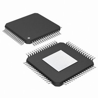
PIC24FJ256DA210T-I/BG Microchip Technology, PIC24FJ256DA210T-I/BG Datasheet - Page 233

PIC24FJ256DA210T-I/BG
Manufacturer Part Number
PIC24FJ256DA210T-I/BG
Description
16-bit, 256KB Flash, 96K RAM, USB, Graphics 121 XBGA 10x10x1.20mm T/R
Manufacturer
Microchip Technology
Series
PIC® 24Fr
Specifications of PIC24FJ256DA210T-I/BG
Core Processor
PIC
Core Size
16-Bit
Speed
32MHz
Connectivity
I²C, IrDA, SPI, UART/USART, USB OTG
Peripherals
Brown-out Detect/Reset, GFX, LVD, POR, PWM, WDT
Number Of I /o
84
Program Memory Size
256KB (85.5K x 24)
Program Memory Type
FLASH
Ram Size
96K x 8
Voltage - Supply (vcc/vdd)
2.2 V ~ 3.6 V
Data Converters
A/D 24x10b
Oscillator Type
Internal
Operating Temperature
-40°C ~ 85°C
Package / Case
121-TFBGA
Lead Free Status / RoHS Status
Lead free / RoHS Compliant
Eeprom Size
-
Lead Free Status / RoHS Status
Lead free / RoHS Compliant
Available stocks
Company
Part Number
Manufacturer
Quantity
Price
Company:
Part Number:
PIC24FJ256DA210T-I/BG
Manufacturer:
Microchip Technology
Quantity:
10 000
- Current page: 233 of 408
- Download datasheet (4Mb)
17.2
1.
2.
3.
4.
5.
6.
17.3
1.
2.
3.
4.
5.
6.
17.4
The following sequence will send a message frame
header, made up of a Break, followed by an auto-baud
Sync byte.
1.
2.
3.
4.
5.
2010 Microchip Technology Inc.
Set up the UART:
a)
b)
c)
Enable the UART.
Set the UTXEN bit (causes a transmit interrupt
two cycles after being set).
Write a data byte to the lower byte of UxTXREG
word. The value will be immediately transferred
to the Transmit Shift Register (TSR) and the
serial bit stream will start shifting out with the
next rising edge of the baud clock.
Alternately, the data byte may be transferred
while UTXEN = 0 and then the user may set
UTXEN. This will cause the serial bit stream to
begin immediately because the baud clock will
start from a cleared state.
A transmit interrupt will be generated as per
interrupt control bit, UTXISELx.
Set up the UART (as described in Section 17.2
“Transmitting in 8-Bit Data Mode”).
Enable the UART.
Set the UTXEN bit (causes a transmit interrupt).
Write UxTXREG as a 16-bit value only.
A word write to UxTXREG triggers the transfer
of the 9-bit data to the TSR. The serial bit stream
will start shifting out with the first rising edge of
the baud clock.
A transmit interrupt will be generated as per the
setting of control bit, UTXISELx.
Configure the UART for the desired mode.
Set UTXEN and UTXBRK to set up the Break
character.
Load the UxTXREG with a dummy character to
initiate transmission (value is ignored).
Write ‘55h’ to UxTXREG; this loads the Sync
character into the transmit FIFO.
After the Break has been sent, the UTXBRK bit
is reset by hardware. The Sync character now
transmits.
Transmitting in 8-Bit Data Mode
Write appropriate values for data, parity and
Stop bits.
Write appropriate baud rate value to the
UxBRG register.
Set up transmit and receive interrupt enable
and priority bits.
Transmitting in 9-Bit Data Mode
Break and Sync Transmit
Sequence
PIC24FJ256DA210 FAMILY
17.5
1.
2.
3.
4.
5.
The act of reading the UxRXREG character will move
the next character to the top of the receive FIFO,
including a new set of PERR and FERR values.
17.6
UARTx Clear to Send (UxCTS) and Request to Send
(UxRTS) are the two hardware controlled pins that are
associated with the UART module. These two pins
allow the UART to operate in Simplex and Flow Control
mode. They are implemented to control the transmis-
sion and reception between the Data Terminal
Equipment (DTE). The UEN<1:0> bits in the UxMODE
register configure these pins.
17.7
The UART module provides two types of infrared UART
support: one is the IrDA clock output to support an
external IrDA encoder and decoder device (legacy
module support), and the other is the full implementa-
tion of the IrDA encoder and decoder. Note that
because the IrDA modes require a 16x baud clock, they
will only work when the BRGH bit (UxMODE<3>) is ‘0’.
17.7.1
To support external IrDA encoder and decoder devices,
the BCLKx pin (same as the UxRTS pin) can be
configured to generate the 16x baud clock. With
UEN<1:0> = 11, the BCLKx pin will output the 16x
baud clock if the UART module is enabled. It can be
used to support the IrDA codec chip.
17.7.2
The UART has full implementation of the IrDA encoder
and decoder as part of the UART module. The built-in
IrDA encoder and decoder functionality is enabled
using the IREN bit (UxMODE<12>). When enabled
(IREN = 1), the receive pin (UxRX) acts as the input
from the infrared receiver. The transmit pin (UxTX) acts
as the output to the infrared transmitter.
Set up the UART (as described in Section 17.2
“Transmitting in 8-Bit Data Mode”).
Enable the UART.
A receive interrupt will be generated when one
or more data characters have been received as
per interrupt control bit, URXISELx.
Read the OERR bit to determine if an overrun
error has occurred. The OERR bit must be reset
in software.
Read UxRXREG.
Receiving in 8-Bit or 9-Bit Data
Mode
Operation of UxCTS and UxRTS
Control Pins
Infrared Support
IrDA CLOCK OUTPUT FOR
EXTERNAL IrDA SUPPORT
BUILT-IN IrDA ENCODER AND
DECODER
DS39969B-page 233
Related parts for PIC24FJ256DA210T-I/BG
Image
Part Number
Description
Manufacturer
Datasheet
Request
R

Part Number:
Description:
Manufacturer:
Microchip Technology Inc.
Datasheet:

Part Number:
Description:
Manufacturer:
Microchip Technology Inc.
Datasheet:

Part Number:
Description:
Manufacturer:
Microchip Technology Inc.
Datasheet:

Part Number:
Description:
Manufacturer:
Microchip Technology Inc.
Datasheet:

Part Number:
Description:
Manufacturer:
Microchip Technology Inc.
Datasheet:

Part Number:
Description:
Manufacturer:
Microchip Technology Inc.
Datasheet:

Part Number:
Description:
Manufacturer:
Microchip Technology Inc.
Datasheet:

Part Number:
Description:
Manufacturer:
Microchip Technology Inc.
Datasheet:


