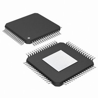
PIC24FJ256DA210T-I/BG Microchip Technology, PIC24FJ256DA210T-I/BG Datasheet - Page 400

PIC24FJ256DA210T-I/BG
Manufacturer Part Number
PIC24FJ256DA210T-I/BG
Description
16-bit, 256KB Flash, 96K RAM, USB, Graphics 121 XBGA 10x10x1.20mm T/R
Manufacturer
Microchip Technology
Series
PIC® 24Fr
Specifications of PIC24FJ256DA210T-I/BG
Core Processor
PIC
Core Size
16-Bit
Speed
32MHz
Connectivity
I²C, IrDA, SPI, UART/USART, USB OTG
Peripherals
Brown-out Detect/Reset, GFX, LVD, POR, PWM, WDT
Number Of I /o
84
Program Memory Size
256KB (85.5K x 24)
Program Memory Type
FLASH
Ram Size
96K x 8
Voltage - Supply (vcc/vdd)
2.2 V ~ 3.6 V
Data Converters
A/D 24x10b
Oscillator Type
Internal
Operating Temperature
-40°C ~ 85°C
Package / Case
121-TFBGA
Lead Free Status / RoHS Status
Lead free / RoHS Compliant
Eeprom Size
-
Lead Free Status / RoHS Status
Lead free / RoHS Compliant
Available stocks
Company
Part Number
Manufacturer
Quantity
Price
Company:
Part Number:
PIC24FJ256DA210T-I/BG
Manufacturer:
Microchip Technology
Quantity:
10 000
- Current page: 400 of 408
- Download datasheet (4Mb)
PIC24FJ256DA210 FAMILY
CTMU
Customer Change Notification Service ............................. 405
Customer Notification Service........................................... 405
Customer Support ............................................................. 405
D
Data Memory
DC Characteristics
Development Support ....................................................... 359
Device Features
Doze Mode........................................................................ 156
E
EDS................................................................................... 273
Electrical Characteristics
Enhanced Parallel Master Port. See EPMP...................... 273
ENVREG Pin..................................................................... 354
EPMP ................................................................................ 273
Equations
Errata .................................................................................. 14
DS39969B-page 400
Measuring Capacitance ............................................ 343
Measuring Time ........................................................ 344
Pulse Delay and Generation ..................................... 344
Address Space............................................................ 47
Memory Map ............................................................... 48
Near Data Space ........................................................ 49
SFR Space.................................................................. 49
Software Stack ............................................................ 75
Space Organization, Alignment .................................. 49
I/O Pin Input Specifications ....................................... 377
I/O Pin Output Specifications .................................... 378
Program Memory ...................................................... 378
100/121--Pin ............................................................... 19
64-Pin.......................................................................... 18
A/D Specifications ..................................................... 384
Absolute Maximum Ratings ...................................... 371
Capacitive Loading on Output Pin ............................ 380
External Clock Timing ............................................... 381
Idle Current ............................................................... 375
Load Conditions and Requirements for
Operating Current ..................................................... 374
PLL Clock Timing Specifications............................... 381
Power-Down Current ................................................ 376
RC Oscillator Start-up Time ...................................... 382
Reset and Brown-out Reset Requirements .............. 382
Temperature and Voltage Specifications .................. 373
Thermal Conditions ................................................... 372
V/F Graph ................................................................. 372
Voltage Regulator Specifications .............................. 379
Alternative Master ..................................................... 273
Key Features............................................................. 273
Master Port Pins ....................................................... 274
16-Bit, 32-Bit CRC Polynomials ................................ 298
A/D Conversion Clock Period ................................... 332
Baud Rate Reload Calculation .................................. 225
Calculating the PWM Period ..................................... 204
Calculation for Maximum PWM Resolution............... 205
Estimating USB Transceiver Current
Relationship Between Device and SPI
RTCC Calibration ...................................................... 294
UART Baud Rate with BRGH = 0 ............................. 232
UART Baud Rate with BRGH = 1 ............................. 232
Specifications.................................................... 379
Consumption..................................................... 243
Clock Speed...................................................... 221
F
Flash Configuration Words ......................................... 46, 347
Flash Program Memory ...................................................... 81
G
Graphics Controller (GFX) ................................................ 305
Graphics Controller Module (GFX) ................................... 305
Graphics Display Module
Graphics Display Module (GFX) ....................................... 305
I
I/O Ports
I
Idle Mode .......................................................................... 156
Input Capture
Input Capture with Dedicated Timers ............................... 197
Input Voltage Levels for Port or Pin
Instruction Set
Instruction-Based Power-Saving Modes................... 155, 156
Interfacing Program and Data Spaces................................ 75
Inter-Integrated Circuit. See I
Internet Address ............................................................... 405
Interrupt Vector Table (IVT) ................................................ 93
Interrupts
J
JTAG Interface.................................................................. 358
2
C
and Table Instructions ................................................ 81
Enhanced ICSP Operation ......................................... 82
JTAG Operation.......................................................... 82
Programming Algorithm .............................................. 84
RTSP Operation ......................................................... 82
Single-Word Programming ......................................... 86
Key Features ............................................................ 305
Display Clock (GCLK) Source .................................. 324
Display Configuration................................................ 324
Memory Locations .................................................... 324
Memory Requirements ............................................. 324
Module Registers...................................................... 306
Analog Port Pins Configuration................................. 158
Analog/Digital Function of an I/O Pin........................ 158
Input Change Notification ......................................... 163
Open-Drain Configuration......................................... 158
Parallel (PIO) ............................................................ 157
Peripheral Pin Select ................................................ 164
Pull-ups and Pull-downs ........................................... 163
Selectable Input Sources.......................................... 165
Clock Rates .............................................................. 225
Reserved Addresses ................................................ 225
Setting Baud Rate as Bus Master............................. 225
Slave Address Masking ............................................ 225
32-Bit Mode .............................................................. 198
Operations ................................................................ 198
Synchronous and Trigger Modes.............................. 197
Tolerated Description Input....................................... 158
Overview................................................................... 365
Summary .................................................................. 363
Control and Status Registers...................................... 96
Implemented Vectors.................................................. 95
Reset Sequence ......................................................... 93
Setup and Service Procedures ................................. 140
Trap Vectors ............................................................... 94
Vector Table ............................................................... 94
2010 Microchip Technology Inc.
2
C. ...................................... 223
Related parts for PIC24FJ256DA210T-I/BG
Image
Part Number
Description
Manufacturer
Datasheet
Request
R

Part Number:
Description:
Manufacturer:
Microchip Technology Inc.
Datasheet:

Part Number:
Description:
Manufacturer:
Microchip Technology Inc.
Datasheet:

Part Number:
Description:
Manufacturer:
Microchip Technology Inc.
Datasheet:

Part Number:
Description:
Manufacturer:
Microchip Technology Inc.
Datasheet:

Part Number:
Description:
Manufacturer:
Microchip Technology Inc.
Datasheet:

Part Number:
Description:
Manufacturer:
Microchip Technology Inc.
Datasheet:

Part Number:
Description:
Manufacturer:
Microchip Technology Inc.
Datasheet:

Part Number:
Description:
Manufacturer:
Microchip Technology Inc.
Datasheet:


