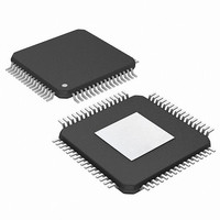
PIC24FJ256DA210T-I/BG Microchip Technology, PIC24FJ256DA210T-I/BG Datasheet - Page 250

PIC24FJ256DA210T-I/BG
Manufacturer Part Number
PIC24FJ256DA210T-I/BG
Description
16-bit, 256KB Flash, 96K RAM, USB, Graphics 121 XBGA 10x10x1.20mm T/R
Manufacturer
Microchip Technology
Series
PIC® 24Fr
Specifications of PIC24FJ256DA210T-I/BG
Core Processor
PIC
Core Size
16-Bit
Speed
32MHz
Connectivity
I²C, IrDA, SPI, UART/USART, USB OTG
Peripherals
Brown-out Detect/Reset, GFX, LVD, POR, PWM, WDT
Number Of I /o
84
Program Memory Size
256KB (85.5K x 24)
Program Memory Type
FLASH
Ram Size
96K x 8
Voltage - Supply (vcc/vdd)
2.2 V ~ 3.6 V
Data Converters
A/D 24x10b
Oscillator Type
Internal
Operating Temperature
-40°C ~ 85°C
Package / Case
121-TFBGA
Lead Free Status / RoHS Status
Lead free / RoHS Compliant
Eeprom Size
-
Lead Free Status / RoHS Status
Lead free / RoHS Compliant
Available stocks
Company
Part Number
Manufacturer
Quantity
Price
Company:
Part Number:
PIC24FJ256DA210T-I/BG
Manufacturer:
Microchip Technology
Quantity:
10 000
- Current page: 250 of 408
- Download datasheet (4Mb)
PIC24FJ256DA210 FAMILY
18.4.2
1.
2.
3.
4.
18.4.3
1.
2.
3.
4.
DS39969B-page 250
Attach to a USB host and enumerate as described
in “Chapter 9 of the USB 2.0 Specification”.
Create a data buffer and populate it with the data
to send to the host.
In the appropriate (even or odd) TX BD for the
desired endpoint:
a)
b)
c)
When the USB module receives an IN token, it
automatically transmits the data in the buffer.
Upon completion, the module updates the status
register (BDnSTAT) and sets the Transfer
Complete Interrupt Flag, TRNIF (U1IR<3>).
Attach to a USB host and enumerate as
described in “Chapter 9 of the USB 2.0
Specification”.
Create a data buffer with the amount of data you
are expecting from the host.
In the appropriate (even or odd) TX BD for the
desired endpoint:
a)
b)
c)
When the USB module receives an OUT token,
it automatically receives the data sent by the
host to the buffer. Upon completion, the module
updates the status register (BDnSTAT) and sets
the Transfer Complete Interrupt Flag, TRNIF
(U1IR<3>).
Set up the status register (BDnSTAT) with
the correct data toggle (DATA0/1) value and
the byte count of the data buffer.
Set up the address register (BDnADR) with
the starting address of the data buffer.
Set the UOWN bit of the status register to
‘1’.
Set up the status register (BDnSTAT) with
the correct data toggle (DATA0/1) value and
the byte count of the data buffer.
Set up the address register (BDnADR) with
the starting address of the data buffer.
Set the UOWN bit of the status register to
‘1’.
RECEIVING AN IN TOKEN IN
DEVICE MODE
RECEIVING AN OUT TOKEN IN
DEVICE MODE
software is responsible for the Acknowledge portion of
Endpoint 0 Control register (U1EP0) and Buffer
Descriptors.
18.5
The following sections describe how to perform common
Host mode tasks. In Host mode, USB transfers are
invoked explicitly by the host software. The host
the transfer. Also, all transfers are performed using the
18.5.1
1.
2.
3.
4.
5.
6.
7.
8.
9.
10. Perform enumeration as described by “Chapter 9
Enable Host mode by setting the HOSTEN bit
(U1CON<3>). This causes the Host mode con-
trol bits in other USB OTG registers to become
available.
Enable the D+ and D- pull-down resistors by set-
ting the DPPULDWN and DMPULDWN bits
(U1OTGCON<5:4>). Disable the D+ and D-
pull-up resistors by clearing the DPPULUP and
DMPULUP bits (U1OTGCON<7:6>).
At this point, SOF generation begins with the
SOF counter loaded with 12,000. Eliminate
noise on the USB by clearing the SOFEN bit
(U1CON<0>) to disable Start-Of-Frame packet
generation.
Enable the device attached interrupt by setting
the ATTACHIE bit (U1IE<6>).
Wait
(U1IR<6> = 1). This is signaled by the USB
device changing the state of D+ or D- from ‘0’
to ‘1’ (SE0 to J state). After it occurs, wait
100 ms for the device power to stabilize.
Check the state of the JSTATE and SE0 bits in
U1CON. If the JSTATE bit (U1CON<7>) is ‘0’,
the connecting device is low speed. If the con-
necting device is low speed, set the low
LSPDEN and LSPD bits (U1ADDR<7> and
U1EP0<7>) to enable low-speed operation.
Reset the USB device by setting the USBRST
bit (U1CON<4>) for at least 50 ms, sending
Reset signaling on the bus. After 50 ms,
terminate the Reset by clearing USBRST.
In order to keep the connected device from
going into suspend, enable the SOF packet
generation by setting the SOFEN bit.
Wait 10 ms for the device to recover from Reset.
of the USB 2.0 Specification”.
Host Mode Operation
for
ENABLE HOST MODE AND
DISCOVER A CONNECTED DEVICE
the
device
2010 Microchip Technology Inc.
attached
interrupt
Related parts for PIC24FJ256DA210T-I/BG
Image
Part Number
Description
Manufacturer
Datasheet
Request
R

Part Number:
Description:
Manufacturer:
Microchip Technology Inc.
Datasheet:

Part Number:
Description:
Manufacturer:
Microchip Technology Inc.
Datasheet:

Part Number:
Description:
Manufacturer:
Microchip Technology Inc.
Datasheet:

Part Number:
Description:
Manufacturer:
Microchip Technology Inc.
Datasheet:

Part Number:
Description:
Manufacturer:
Microchip Technology Inc.
Datasheet:

Part Number:
Description:
Manufacturer:
Microchip Technology Inc.
Datasheet:

Part Number:
Description:
Manufacturer:
Microchip Technology Inc.
Datasheet:

Part Number:
Description:
Manufacturer:
Microchip Technology Inc.
Datasheet:


