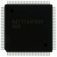
HD6417144F50V Renesas Electronics America, HD6417144F50V Datasheet - Page 44

HD6417144F50V
Manufacturer Part Number
HD6417144F50V
Description
IC SUPERH MCU ROMLESS 112QFP
Manufacturer
Renesas Electronics America
Series
SuperH® SH7144r
Datasheet
1.HD64F7144F50V.pdf
(932 pages)
Specifications of HD6417144F50V
Core Processor
SH-2
Core Size
32-Bit
Speed
50MHz
Connectivity
EBI/EMI, I²C, SCI
Peripherals
DMA, POR, PWM, WDT
Number Of I /o
74
Program Memory Type
ROMless
Ram Size
8K x 8
Voltage - Supply (vcc/vdd)
3 V ~ 3.6 V
Data Converters
A/D 8x10b
Oscillator Type
Internal
Operating Temperature
-20°C ~ 75°C
Package / Case
112-QFP
For Use With
HS0005KCU11H - EMULATOR E10A-USB H8S(X),SH2(A)EDK7145 - DEV EVALUATION KIT SH7145
Lead Free Status / RoHS Status
Lead free / RoHS Compliant
Eeprom Size
-
Program Memory Size
-
Available stocks
Company
Part Number
Manufacturer
Quantity
Price
Company:
Part Number:
HD6417144F50V
Manufacturer:
Renesas Electronics America
Quantity:
10 000
- Current page: 44 of 932
- Download datasheet (6Mb)
Table 13.3
Table 13.3
Table 13.3
Table 13.3
Table 13.4
Table 13.5
Table 13.6
Table 13.6
Table 13.6
Table 13.6
Table 13.7
Table 13.8
Table 13.9
Table 13.10
Table 13.11
Table 13.12
Table 13.13
Section 14 I
Table 14.1
Table 14.2
Table 14.3
Table 14.4
Table 14.5
Table 14.6
Table 14.7
Table 14.8
Table 14.9
Table 14.10
Section 15 A/D Converter
Table 15.1
Table 15.2
Table 15.3
Table 15.4
Table 15.5
Table 15.6
Rev.4.00 Mar. 27, 2008 Page xlii of xliv
REJ09B0108-0400
2
C Bus Interface (IIC) Option
BRR Settings for Various Bit Rates (Asynchronous Mode) (1) ........................... 418
BRR Settings for Various Bit Rates (Asynchronous Mode) (2) ........................... 418
BRR Settings for Various Bit Rates (Asynchronous Mode) (3) ........................... 419
BRR Settings for Various Bit Rates (Asynchronous Mode) (4) ........................... 419
Maximum Bit Rate for Each Frequency when Using Baud Rate Generator
(Asynchronous Mode) .......................................................................................... 420
Maximum Bit Rate with External Clock Input (Asynchronous Mode) ................ 421
BRR Settings for Various Bit Rates (Clocked Synchronous Mode) (1) ............... 422
BRR Settings for Various Bit Rates (Clocked Synchronous Mode) (2) ............... 422
BRR Settings for Various Bit Rates (Clocked Synchronous Mode) (3) ............... 423
BRR Settings for Various Bit Rates (Clocked Synchronous Mode) (4) ............... 423
Maximum Bit Rate with External Clock Input (Clocked Synchronous Mode) .... 424
Examples of Bit Rate for Various BRR Settings (Smart Card Interface Mode)
(When n = 0 and S = 372)..................................................................................... 425
Maximum Bit Rate at Various Frequencies (Smart Card Interface Mode)
(when S = 372)...................................................................................................... 425
Pin Configuration.................................................................................................. 470
Transfer Format .................................................................................................... 473
Setting of the Transfer Rate .................................................................................. 476
The Relationship between Flags and Transfer States (Master Mode)................... 483
The Relationship between Flags and Transfer States (Slave Mode)..................... 484
I
Examples of Operations in which the DTC Is Used ............................................. 525
I
Tolerance of the SCL Rise Time (t
Pin Configuration.................................................................................................. 543
Channel Select List ............................................................................................... 546
A/D Conversion Time (Single Mode)................................................................... 551
A/D Conversion Time (Scan Mode) ..................................................................... 552
A/D Converter Interrupt Sources .......................................................................... 553
Analog Pin Specifications..................................................................................... 558
Serial Transfer Formats (Asynchronous Mode).................................................... 427
SSR Status Flags and Receive Data Handling ...................................................... 434
Interrupt Sources in Serial Communication Interface Mode ................................ 461
Interrupt Sources in Smart Card Interface Mode .................................................. 462
I
2
2
2
C Bus Data Format: Description of Symbols ..................................................... 494
C Bus Timing (output of SCL and SDA) ........................................................... 528
C Bus Timing (when the effect of t
Sr
) .................................................................... 529
Sr
/t
Sf
Is at its maximum)................................ 531
Related parts for HD6417144F50V
Image
Part Number
Description
Manufacturer
Datasheet
Request
R

Part Number:
Description:
KIT STARTER FOR M16C/29
Manufacturer:
Renesas Electronics America
Datasheet:

Part Number:
Description:
KIT STARTER FOR R8C/2D
Manufacturer:
Renesas Electronics America
Datasheet:

Part Number:
Description:
R0K33062P STARTER KIT
Manufacturer:
Renesas Electronics America
Datasheet:

Part Number:
Description:
KIT STARTER FOR R8C/23 E8A
Manufacturer:
Renesas Electronics America
Datasheet:

Part Number:
Description:
KIT STARTER FOR R8C/25
Manufacturer:
Renesas Electronics America
Datasheet:

Part Number:
Description:
KIT STARTER H8S2456 SHARPE DSPLY
Manufacturer:
Renesas Electronics America
Datasheet:

Part Number:
Description:
KIT STARTER FOR R8C38C
Manufacturer:
Renesas Electronics America
Datasheet:

Part Number:
Description:
KIT STARTER FOR R8C35C
Manufacturer:
Renesas Electronics America
Datasheet:

Part Number:
Description:
KIT STARTER FOR R8CL3AC+LCD APPS
Manufacturer:
Renesas Electronics America
Datasheet:

Part Number:
Description:
KIT STARTER FOR RX610
Manufacturer:
Renesas Electronics America
Datasheet:

Part Number:
Description:
KIT STARTER FOR R32C/118
Manufacturer:
Renesas Electronics America
Datasheet:

Part Number:
Description:
KIT DEV RSK-R8C/26-29
Manufacturer:
Renesas Electronics America
Datasheet:

Part Number:
Description:
KIT STARTER FOR SH7124
Manufacturer:
Renesas Electronics America
Datasheet:

Part Number:
Description:
KIT STARTER FOR H8SX/1622
Manufacturer:
Renesas Electronics America
Datasheet:

Part Number:
Description:
KIT DEV FOR SH7203
Manufacturer:
Renesas Electronics America
Datasheet:


