NUC100LC1BN Nuvoton Technology Corporation of America, NUC100LC1BN Datasheet - Page 313
NUC100LC1BN
Manufacturer Part Number
NUC100LC1BN
Description
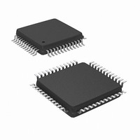
IC MCU 32BIT 32KB FLASH 48LQFP
Manufacturer
Nuvoton Technology Corporation of America
Series
NuMicro™r
Specifications of NUC100LC1BN
Core Processor
ARM Cortex-M0
Core Size
32-Bit
Speed
50MHz
Connectivity
I²C, IrDA, SPI, UART/USART
Peripherals
Brown-out Detect/Reset, DMA, I²S, LVD, POR, PS2, PWM, WDT
Number Of I /o
35
Program Memory Size
32KB (32K x 8)
Program Memory Type
FLASH
Ram Size
4K x 8
Voltage - Supply (vcc/vdd)
2.5 V ~ 5.5 V
Data Converters
A/D 8x12b
Oscillator Type
Internal
Operating Temperature
-40°C ~ 85°C
Package / Case
48-LQFP
Lead Free Status / RoHS Status
Lead free / RoHS Compliant
Eeprom Size
-
Available stocks
Company
Part Number
Manufacturer
Quantity
Price
Company:

Part Number:
NUC100LC1BN
Manufacturer:
NuvoTon
Quantity:
1 600
Company:
Part Number:
NUC100LC1BN
Manufacturer:
Nuvoton Technology Corporation of America
Quantity:
10 000
Part Number:
NUC100LC1BN
Manufacturer:
NUVOTON
Quantity:
20 000


[18]
[17]
[16]
[15:8]
[7]
[6]
[5]
[4]
[3]
NuMicro™ NUC100 Series Technical Reference Manual
FL_IE1
RL_IE1
INV1
Reserved
CFLRI0
CRLRI0
Reserved
CAPIF0
CAPCH0EN
0 = Disable capture function on PWM group channel 1
When Enable, Capture latched the PWM-counter and saved to CRLR (Rising latch)
and CFLR (Falling latch).
When Disable, Capture does not update CRLR and CFLR, and disable PWM group
channel 1 Interrupt.
Channel 1 Falling Latch Interrupt Enable
1 = Enable falling latch interrupt
0 = Disable falling latch interrupt
When Enable, if Capture detects PWM group channel 1 has falling transition, Capture
issues an Interrupt.
Channel 1 Rising Latch Interrupt Enable
1 = Enable rising latch interrupt
0 = Disable rising latch interrupt
When Enable, if Capture detects PWM group channel 1 has rising transition, Capture
issues an Interrupt.
Channel 1 Inverter Enable
1 = Inverter enable. Reverse the input signal from GPIO before fed to Capture timer
0 = Inverter disable
Reserved
CFLR0 Latched Indicator Bit
When PWM group input channel 0 has a falling transition, CFLR0 was latched with the
value of PWM down-counter and this bit is set by hardware.
In Medium Density, software can write 0 to clear this bit to zero.
In Low Density, software can write 0 to clear this bit to zero if BCn bit is 0, and can
Write 1 to clear this bit to zero if BCn bit is 1.
CRLR0 Latched Indicator Bit
When PWM group input channel 0 has a rising transition, CRLR0 was latched with the
value of PWM down-counter and this bit is set by hardware.
In Medium Density, software can write 0 to clear this bit to zero.
In Low Density, software can write 0 to clear this bit to zero if BCn bit is 0, and can
Write 1 to clear this bit to zero if BCn bit is 1.
Reserved
Channel 0 Capture Interrupt Indication Flag
If PWM group channel 0 rising latch interrupt is enabled (CRL_IE0=1), a rising
transition occurs at PWM group channel 0 will result in CAPIF0 to high; Similarly, a
falling transition will cause CAPIF0 to be set high if PWM group channel 0 falling latch
interrupt is enabled (CFL_IE0=1).
Write 1 to clear this bit to zero
Channel 0 Capture Function Enable
1 = Enable capture function on PWM group channel 0.
0 = Disable capture function on PWM group channel 0
When Enable, Capture latched the PWM-counter value and saved to CRLR (Rising
latch) and CFLR (Falling latch).
When Disable, Capture does not update CRLR and CFLR, and disable PWM group
channel 0 Interrupt.
- 313 -
Publication Release Date: Oct 22, 2010
Revision V1.06
Related parts for NUC100LC1BN
Image
Part Number
Description
Manufacturer
Datasheet
Request
R

Part Number:
Description:
Manufacturer:
Nuvoton Technology Corporation of America
Datasheet:
Part Number:
Description:
Manufacturer:
Nuvoton Technology Corporation of America
Datasheet:
Part Number:
Description:
Manufacturer:
Nuvoton Technology Corporation of America
Datasheet:
Part Number:
Description:
Manufacturer:
Nuvoton Technology Corporation of America
Datasheet:
Part Number:
Description:
Manufacturer:
Nuvoton Technology Corporation of America
Datasheet:
Part Number:
Description:
Manufacturer:
Nuvoton Technology Corporation of America
Datasheet:
Part Number:
Description:
Manufacturer:
Nuvoton Technology Corporation of America
Datasheet: