ATSAM3U-EK Atmel, ATSAM3U-EK Datasheet - Page 19
ATSAM3U-EK
Manufacturer Part Number
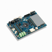
ATSAM3U-EK
Description
KIT EVAL FOR AT91SAM3U CORTEX
Manufacturer
Atmel
Type
MCUr
Datasheets
1.ATSAM3U-EK.pdf
(2 pages)
2.ATSAM3U-EK.pdf
(61 pages)
3.ATSAM3U-EK.pdf
(1171 pages)
4.ATSAM3U-EK.pdf
(53 pages)
Specifications of ATSAM3U-EK
Contents
Board
Processor To Be Evaluated
SAM3U
Data Bus Width
32 bit
Interface Type
RS-232, USB
Operating Supply Voltage
3 V
Silicon Manufacturer
Atmel
Core Architecture
ARM
Core Sub-architecture
Cortex - M3
Silicon Core Number
SAM3U4E
Silicon Family Name
SAM3U
Kit Contents
Board CD Docs
Rohs Compliant
Yes
For Use With/related Products
AT91SAM3U
Lead Free Status / RoHS Status
Lead free / RoHS Compliant
Available stocks
Company
Part Number
Manufacturer
Quantity
Price
Company:

Part Number:
ATSAM3U-EK
Manufacturer:
Atmel
Quantity:
10


5.4
5.5
5.5.1
5.5.2
6430D–ATARM–25-Mar-11
Active Mode
Low Power Modes
Backup Mode
Wait Mode
Active mode is the normal running mode with the core clock running from the fast RC oscillator,
the main crystal oscillator or the PLLA. The power management controller can be used to adapt
the frequency and to disable the peripheral clocks.
The various low power modes of the SAM3U are described below:
The purpose of backup mode is to achieve the lowest power consumption possible in a system
which is performing periodic wake-ups to perform tasks but not requiring fast startup time
(<0.5ms).
The Supply Controller, zero-power power-on reset, RTT, RTC, Backup registers and 32 kHz
Oscillator (RC or crystal oscillator selected by software in the Supply Controller) are running.
The regulator and the core supply are off.
Backup Mode is based on the Cortex-M3 deep-sleep mode with the voltage regulator disabled.
The SAM3U Series can be awakened from this mode through the Force Wake-Up pin (FWUP),
and Wake-Up input pins WKUP0 to WKUP15, Supply Monitor, RTT or RTC wake-up event. Cur-
rent Consumption is 2.5 μA typical on VDDBU.
Backup mode is entered by using WFE instructions with the SLEEPDEEP bit in the System Con-
trol Register of the Cortex-M3 set to 1. (See the “Power Management” description in The “ARM
Cortex M3 Processor” section of the product datasheet).
Exit from Backup mode happens if one of the following enable wake up events occurs:
The purpose of the wait mode is to achieve very low power consumption while maintaining the
whole device in a powered state for a startup time of less than 10 μs.
In this mode, the clocks of the core, peripherals and memories are stopped. However, the core,
peripherals and memories power supplies are still powered. From this mode, a fast start up is
available.
This mode is entered via Wait for Event (WFE) instructions with LPM = 1 (Low Power Mode bit in
PMC_FSMR). The Cortex-M3 is able to handle external events or internal events in order to
wake-up the core (WFE). This is done by configuring the external lines WKUP0-15 as fast
startup wake-up pins (refer to
events can be used to wake up the CPU (exit from WFE).
Current Consumption in Wait mode is typically 15 μA on VDDIN if the internal voltage regulator
is used or 8 μA on VDDCORE if an external regulator is used.
• FWUP pin (low level, configurable debouncing)
• WKUPEN0-15 pins (level transition, configurable debouncing)
• SM alarm
• RTC alarm
• RTT alarm
Section 5.7 “Fast
Start-Up”). RTC or RTT Alarm and USB wake-up
SAM3U Series
19
Related parts for ATSAM3U-EK
Image
Part Number
Description
Manufacturer
Datasheet
Request
R

Part Number:
Description:
AT91 ARM Thumb-based Microcontrollers
Manufacturer:
ATMEL [ATMEL Corporation]
Datasheet:

Part Number:
Description:
DEV KIT FOR AVR/AVR32
Manufacturer:
Atmel
Datasheet:

Part Number:
Description:
INTERVAL AND WIPE/WASH WIPER CONTROL IC WITH DELAY
Manufacturer:
ATMEL Corporation
Datasheet:
Part Number:
Description:
Low-Voltage Voice-Switched IC for Hands-Free Operation
Manufacturer:
ATMEL Corporation
Datasheet:
Part Number:
Description:
MONOLITHIC INTEGRATED FEATUREPHONE CIRCUIT
Manufacturer:
ATMEL Corporation
Datasheet:
Part Number:
Description:
AM-FM Receiver IC U4255BM-M
Manufacturer:
ATMEL Corporation
Datasheet:
Part Number:
Description:
Monolithic Integrated Feature Phone Circuit
Manufacturer:
ATMEL Corporation
Datasheet:
Part Number:
Description:
Multistandard Video-IF and Quasi Parallel Sound Processing
Manufacturer:
ATMEL Corporation
Datasheet:
Part Number:
Description:
High-performance EE PLD
Manufacturer:
ATMEL Corporation
Datasheet:
Part Number:
Description:
8-bit Flash Microcontroller
Manufacturer:
ATMEL Corporation
Datasheet:
Part Number:
Description:
2-Wire Serial EEPROM
Manufacturer:
ATMEL Corporation
Datasheet: