ATSAM3U-EK Atmel, ATSAM3U-EK Datasheet - Page 874
ATSAM3U-EK
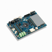
Manufacturer Part Number
ATSAM3U-EK
Description
KIT EVAL FOR AT91SAM3U CORTEX
Manufacturer
Atmel
Type
MCUr
Datasheets
1.ATSAM3U-EK.pdf
(2 pages)
2.ATSAM3U-EK.pdf
(61 pages)
3.ATSAM3U-EK.pdf
(1171 pages)
4.ATSAM3U-EK.pdf
(53 pages)
Specifications of ATSAM3U-EK
Contents
Board
Processor To Be Evaluated
SAM3U
Data Bus Width
32 bit
Interface Type
RS-232, USB
Operating Supply Voltage
3 V
Silicon Manufacturer
Atmel
Core Architecture
ARM
Core Sub-architecture
Cortex - M3
Silicon Core Number
SAM3U4E
Silicon Family Name
SAM3U
Kit Contents
Board CD Docs
Rohs Compliant
Yes
For Use With/related Products
AT91SAM3U
Lead Free Status / RoHS Status
Lead free / RoHS Compliant
Available stocks
Company
Part Number
Manufacturer
Quantity
Price
Company:

Part Number:
ATSAM3U-EK
Manufacturer:
Atmel
Quantity:
10


38.6.2.5
Figure 38-8. Fault Protection
874
874
fault input 0
fault input 1
fault input y
SAM3U Series
SAM3U Series
Fault Protection
Glitch
Filter
Glitch
Filter
FFIL0
FFIL1
0
1
0
1
4 inputs provide fault protection which can force any of the PWM output pair to a programmable
value. This mechanism has priority over output overriding.
The polarity level of the fault inputs is configured by the FPOL field in the
Register”
Counter, to name but a few, the polarity level must be FPOL = 1. For fault inputs coming from
external GPIO pins the polarity level depends on the user's implementation.
The configuration of the Fault Activation Mode (FMOD bit in PWMC_FMR) depends on the
peripheral generating the fault. If the corresponding peripheral does not have “Fault Clear” man-
agement, then the FMOD configuration to use must be FMOD = 1, to avoid spurious fault
detection. Check the corresponding peripheral documentation for details on handling fault
generation.
The fault inputs can be glitch filtered or not in function of the FFIL field in the PWM_FMR regis-
ter. When the filter is activated, glitches on fault inputs with a width inferior to the PWM master
clock (MCK) period are rejected.
A fault becomes active as soon as its corresponding fault input has a transition to the pro-
grammed polarity level. If the corresponding bit FMOD is set to 0 in the PWM_FMR register, the
fault remains active as long as the fault input is at this polarity level. If the corresponding FMOD
bit is set to 1, the fault remains active until the fault input is not at this polarity level anymore and
until it is cleared by writing the corresponding bit FCLR in the
(PWM_FSCR). By reading the
current level of the fault inputs by means of the field FIV, and can know which fault is currently
active thanks to the FS field.
Each fault can be taken into account or not by the fault protection mechanism in each channel.
To be taken into account in the channel x, the fault y must be enabled by the bit FPEx[y] in the
“PWM Fault Protection Enable Registers” (PWM_FPE1). However the synchronous channels
(see
of the channel 0 (bits FPE0[y]).
The fault protection on a channel is triggered when this channel is enabled and when any one of
the faults that are enabled for this channel is active. It can be triggered even if the PWM master
clock (MCK) is not running but only by a fault input that is not glitch filtered.
FIV0
FIV1
Section 38.6.2.6 ”Synchronous
FPOL0
FPOL1
=
=
(PWM_FMR). For fault inputs coming from internal peripherals such as ADC, Timer
FMOD0
FMOD1
Write FCLR0 at 1
Write FCLR1 at 1
SET
CLR
SET
CLR
OUT
OUT
“PWM Fault Status Register”
FMOD0
FMOD1
Channels”) do not use their own fault enable bits, but those
0
1
0
1
Fault 0 Status
FS0
Fault 1 Status
FS1
FPEx[1]
FPE0[1]
FPEx[0]
FPE0[0]
SYNCx
SYNCx
0
1
0
1
(PWM_FSR), the user can read the
from fault 0
from fault 1
from fault y
“PWM Fault Clear Register”
From Output
From Output
Override
Override
FPVHx
FPVLx
OOHx
OOLx
6430D–ATARM–25-Mar-11
6430D–ATARM–25-Mar-11
“PWM Fault Mode
Fault protection
channel x
on PWM
0
1
1
0
PWMHx
PWMLx
Related parts for ATSAM3U-EK
Image
Part Number
Description
Manufacturer
Datasheet
Request
R

Part Number:
Description:
AT91 ARM Thumb-based Microcontrollers
Manufacturer:
ATMEL [ATMEL Corporation]
Datasheet:

Part Number:
Description:
DEV KIT FOR AVR/AVR32
Manufacturer:
Atmel
Datasheet:

Part Number:
Description:
INTERVAL AND WIPE/WASH WIPER CONTROL IC WITH DELAY
Manufacturer:
ATMEL Corporation
Datasheet:
Part Number:
Description:
Low-Voltage Voice-Switched IC for Hands-Free Operation
Manufacturer:
ATMEL Corporation
Datasheet:
Part Number:
Description:
MONOLITHIC INTEGRATED FEATUREPHONE CIRCUIT
Manufacturer:
ATMEL Corporation
Datasheet:
Part Number:
Description:
AM-FM Receiver IC U4255BM-M
Manufacturer:
ATMEL Corporation
Datasheet:
Part Number:
Description:
Monolithic Integrated Feature Phone Circuit
Manufacturer:
ATMEL Corporation
Datasheet:
Part Number:
Description:
Multistandard Video-IF and Quasi Parallel Sound Processing
Manufacturer:
ATMEL Corporation
Datasheet:
Part Number:
Description:
High-performance EE PLD
Manufacturer:
ATMEL Corporation
Datasheet:
Part Number:
Description:
8-bit Flash Microcontroller
Manufacturer:
ATMEL Corporation
Datasheet:
Part Number:
Description:
2-Wire Serial EEPROM
Manufacturer:
ATMEL Corporation
Datasheet: