ATSAM3U-EK Atmel, ATSAM3U-EK Datasheet - Page 223
ATSAM3U-EK
Manufacturer Part Number
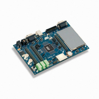
ATSAM3U-EK
Description
KIT EVAL FOR AT91SAM3U CORTEX
Manufacturer
Atmel
Type
MCUr
Datasheets
1.ATSAM3U-EK.pdf
(2 pages)
2.ATSAM3U-EK.pdf
(61 pages)
3.ATSAM3U-EK.pdf
(1171 pages)
4.ATSAM3U-EK.pdf
(53 pages)
Specifications of ATSAM3U-EK
Contents
Board
Processor To Be Evaluated
SAM3U
Data Bus Width
32 bit
Interface Type
RS-232, USB
Operating Supply Voltage
3 V
Silicon Manufacturer
Atmel
Core Architecture
ARM
Core Sub-architecture
Cortex - M3
Silicon Core Number
SAM3U4E
Silicon Family Name
SAM3U
Kit Contents
Board CD Docs
Rohs Compliant
Yes
For Use With/related Products
AT91SAM3U
Lead Free Status / RoHS Status
Lead free / RoHS Compliant
Available stocks
Company
Part Number
Manufacturer
Quantity
Price
Company:

Part Number:
ATSAM3U-EK
Manufacturer:
Atmel
Quantity:
10


13.22.8.2
6430D–ATARM–25-Mar-11
Updating an MPU region using multi-word writes
However, memory barrier instructions are not required if the MPU setup process starts by enter-
ing an exception handler, or is followed by an exception return, because the exception entry and
exception return mechanism cause memory barrier behavior.
Software does not need any memory barrier instructions during MPU setup, because it accesses
the MPU through the PPB, which is a Strongly-Ordered memory region.
For example, if you want all of the memory access behavior to take effect immediately after the
programming sequence, use a DSB instruction and an ISB instruction. A DSB is required after
changing MPU settings, such as at the end of context switch. An ISB is required if the code that
programs the MPU region or regions is entered using a branch or call. If the programming
sequence is entered using a return from exception, or by taking an exception, then you do not
require an ISB.
You can program directly using multi-word writes, depending on how the information is divided.
Consider the following reprogramming:
Use an STM instruction to optimize this:
You can do this in two words for pre-packed information. This means that the RBAR contains the
required region number and had the VALID bit set to 1, see
ter” on page
Use an STM instruction to optimize this:
• before MPU setup if there might be outstanding memory transfers, such as buffered writes,
• after MPU setup if it includes memory transfers that must use the new MPU settings.
that might be affected by the change in MPU settings
; R1 = region number
; R2 = address
; R3 = size, attributes in one
LDR R0, =MPU_RNR
STR R1, [R0, #0x0]
STR R2, [R0, #0x4]
STR R3, [R0, #0x8]
; R1 = region number
; R2 = address
; R3 = size, attributes in one
LDR R0, =MPU_RNR
STM R0, {R1-R3}
; R1 = address and region number in one
; R2 = size and attributes in one
LDR R0, =MPU_RBAR
STR R1, [R0, #0x0]
STR R2, [R0, #0x4]
; R1 = address and region number in one
; R2 = size and attributes in one
LDR R0,=MPU_RBAR
STM R0, {R1-R2}
218. Use this when the data is statically packed, for example in a boot loader:
; 0xE000ED98, MPU region number register
; Region Number
; Region Base Address
; Region Attribute, Size and Enable
; 0xE000ED98, MPU region number register
; Region Number, address, attribute, size and enable
; 0xE000ED9C, MPU Region Base register
; Region base address and
; region number combined with VALID (bit 4) set to 1
; Region Attribute, Size and Enable
; 0xE000ED9C, MPU Region Base register
; Region base address, region number and VALID bit,
“MPU Region Base Address Regis-
SAM3U Series
223
Related parts for ATSAM3U-EK
Image
Part Number
Description
Manufacturer
Datasheet
Request
R

Part Number:
Description:
AT91 ARM Thumb-based Microcontrollers
Manufacturer:
ATMEL [ATMEL Corporation]
Datasheet:

Part Number:
Description:
DEV KIT FOR AVR/AVR32
Manufacturer:
Atmel
Datasheet:

Part Number:
Description:
INTERVAL AND WIPE/WASH WIPER CONTROL IC WITH DELAY
Manufacturer:
ATMEL Corporation
Datasheet:
Part Number:
Description:
Low-Voltage Voice-Switched IC for Hands-Free Operation
Manufacturer:
ATMEL Corporation
Datasheet:
Part Number:
Description:
MONOLITHIC INTEGRATED FEATUREPHONE CIRCUIT
Manufacturer:
ATMEL Corporation
Datasheet:
Part Number:
Description:
AM-FM Receiver IC U4255BM-M
Manufacturer:
ATMEL Corporation
Datasheet:
Part Number:
Description:
Monolithic Integrated Feature Phone Circuit
Manufacturer:
ATMEL Corporation
Datasheet:
Part Number:
Description:
Multistandard Video-IF and Quasi Parallel Sound Processing
Manufacturer:
ATMEL Corporation
Datasheet:
Part Number:
Description:
High-performance EE PLD
Manufacturer:
ATMEL Corporation
Datasheet:
Part Number:
Description:
8-bit Flash Microcontroller
Manufacturer:
ATMEL Corporation
Datasheet:
Part Number:
Description:
2-Wire Serial EEPROM
Manufacturer:
ATMEL Corporation
Datasheet: