ATSAM3U-EK Atmel, ATSAM3U-EK Datasheet - Page 511
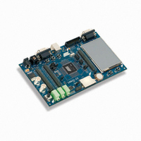
ATSAM3U-EK
Manufacturer Part Number
ATSAM3U-EK
Description
KIT EVAL FOR AT91SAM3U CORTEX
Manufacturer
Atmel
Type
MCUr
Datasheets
1.ATSAM3U-EK.pdf
(2 pages)
2.ATSAM3U-EK.pdf
(61 pages)
3.ATSAM3U-EK.pdf
(1171 pages)
4.ATSAM3U-EK.pdf
(53 pages)
Specifications of ATSAM3U-EK
Contents
Board
Processor To Be Evaluated
SAM3U
Data Bus Width
32 bit
Interface Type
RS-232, USB
Operating Supply Voltage
3 V
Silicon Manufacturer
Atmel
Core Architecture
ARM
Core Sub-architecture
Cortex - M3
Silicon Core Number
SAM3U4E
Silicon Family Name
SAM3U
Kit Contents
Board CD Docs
Rohs Compliant
Yes
For Use With/related Products
AT91SAM3U
Lead Free Status / RoHS Status
Lead free / RoHS Compliant
Available stocks
Company
Part Number
Manufacturer
Quantity
Price
Company:

Part Number:
ATSAM3U-EK
Manufacturer:
Atmel
Quantity:
10


6430D–ATARM–25-Mar-11
6430D–ATARM–25-Mar-11
sive samplings of the input of the I/O line, the PIO Controller clock must be enabled. The Input
Change Interrupt is available, regardless of the configuration of the I/O line, i.e. configured as an
input only, controlled by the PIO Controller or assigned to a peripheral function.
By default, the interrupt can be generated at any time an edge is detected on the input.
Some additional Interrupt modes can be enabled/disabled by writing in the PIO_AIMER (Addi-
tional Interrupt Modes Enable Register) and PIO_AIMDR (Additional Interrupt Modes Disable
Register). The current state of this selection can be read through the PIO_AIMMR (Additional
Interrupt Modes Mask Register)
These Additional Modes are:
In order to select an Additional Interrupt Mode:
When an input Edge or Level is detected on an I/O line, the corresponding bit in PIO_ISR (Inter-
rupt Status Register) is set. If the corresponding bit in PIO_IMR is set, the PIO Controller
interrupt line is asserted. The interrupt signals of the thirty-two channels are ORed-wired
together to generate a single interrupt signal to the Nested Vector Interrupt Controller (NVIC).
When the software reads PIO_ISR, all the interrupts are automatically cleared. This signifies that
all the interrupts that are pending when PIO_ISR is read must be handled. When an Interrupt is
enabled on a “Level”, the interrupt is generated as long as the interrupt source is not cleared,
even if some read accesses in PIO_ISR are performed.
• Rising Edge Detection
• Falling Edge Detection
• Low Level Detection
• High Level Detection
• The type of event detection (Edge or Level) must be selected by writing in the set of registers;
• The Polarity of the event detection (Rising/Falling Edge or High/Low Level) must be selected
PIO_ESR (Edge Select Register) and PIO_LSR (Level Select Register) which enable
respectively, the Edge and Level Detection. The current status of this selection is accessible
through the PIO_ELSR (Edge/Level Status Register).
by writing in the set of registers; PIO_FELLSR (Falling Edge /Low Level Select Register) and
PIO_REHLSR (Rising Edge/High Level Select Register) which allow to select Falling or
Rising Edge (if Edge is selected in the PIO_ELSR) Edge or High or Low Level Detection (if
Level is selected in the PIO_ELSR). The current status of this selection is accessible through
the PIO_FRLHSR (Fall/Rise - Low/High Status Register).
SAM3U Series
SAM3U Series
511
511
Related parts for ATSAM3U-EK
Image
Part Number
Description
Manufacturer
Datasheet
Request
R

Part Number:
Description:
AT91 ARM Thumb-based Microcontrollers
Manufacturer:
ATMEL [ATMEL Corporation]
Datasheet:

Part Number:
Description:
DEV KIT FOR AVR/AVR32
Manufacturer:
Atmel
Datasheet:

Part Number:
Description:
INTERVAL AND WIPE/WASH WIPER CONTROL IC WITH DELAY
Manufacturer:
ATMEL Corporation
Datasheet:
Part Number:
Description:
Low-Voltage Voice-Switched IC for Hands-Free Operation
Manufacturer:
ATMEL Corporation
Datasheet:
Part Number:
Description:
MONOLITHIC INTEGRATED FEATUREPHONE CIRCUIT
Manufacturer:
ATMEL Corporation
Datasheet:
Part Number:
Description:
AM-FM Receiver IC U4255BM-M
Manufacturer:
ATMEL Corporation
Datasheet:
Part Number:
Description:
Monolithic Integrated Feature Phone Circuit
Manufacturer:
ATMEL Corporation
Datasheet:
Part Number:
Description:
Multistandard Video-IF and Quasi Parallel Sound Processing
Manufacturer:
ATMEL Corporation
Datasheet:
Part Number:
Description:
High-performance EE PLD
Manufacturer:
ATMEL Corporation
Datasheet:
Part Number:
Description:
8-bit Flash Microcontroller
Manufacturer:
ATMEL Corporation
Datasheet:
Part Number:
Description:
2-Wire Serial EEPROM
Manufacturer:
ATMEL Corporation
Datasheet: