ATSAM3U-EK Atmel, ATSAM3U-EK Datasheet - Page 869
ATSAM3U-EK
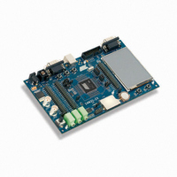
Manufacturer Part Number
ATSAM3U-EK
Description
KIT EVAL FOR AT91SAM3U CORTEX
Manufacturer
Atmel
Type
MCUr
Datasheets
1.ATSAM3U-EK.pdf
(2 pages)
2.ATSAM3U-EK.pdf
(61 pages)
3.ATSAM3U-EK.pdf
(1171 pages)
4.ATSAM3U-EK.pdf
(53 pages)
Specifications of ATSAM3U-EK
Contents
Board
Processor To Be Evaluated
SAM3U
Data Bus Width
32 bit
Interface Type
RS-232, USB
Operating Supply Voltage
3 V
Silicon Manufacturer
Atmel
Core Architecture
ARM
Core Sub-architecture
Cortex - M3
Silicon Core Number
SAM3U4E
Silicon Family Name
SAM3U
Kit Contents
Board CD Docs
Rohs Compliant
Yes
For Use With/related Products
AT91SAM3U
Lead Free Status / RoHS Status
Lead free / RoHS Compliant
Available stocks
Company
Part Number
Manufacturer
Quantity
Price
Company:

Part Number:
ATSAM3U-EK
Manufacturer:
Atmel
Quantity:
10


38.6.2.2
6430D–ATARM–25-Mar-11
6430D–ATARM–25-Mar-11
Comparator
The comparator continuously compares its counter value with the channel period defined by
CPRD in the
defined by CDTY in the
generate an output signal OCx accordingly.
The different properties of the waveform of the output OCx are:
• the clock selection. The channel counter is clocked by one of the clocks provided by the
• the waveform period. This channel parameter is defined in the CPRD field of the
• the waveform duty-cycle. This channel parameter is defined in the CDTY field of the
(
------------------------------------------ -
(
----------------------------------------------------- -
clock generator described in the previous section. This channel parameter is defined in the
CPRE field of the
reset at 0.
PWM_CPRDx register.
If the waveform is left aligned, then the output waveform period depends on the counter
source clock and can be calculated:
By using the PWM master clock (MCK) divided by an X given prescaler value (with X being 1,
2, 4, 8, 16, 32, 64, 128, 256, 512, or 1024), the resulting period formula will be:
By using the PWM master clock (MCK) divided by one of both DIVA or DIVB divider, the
formula becomes, respectively:
If the waveform is center aligned then the output waveform period depends on the counter
source clock and can be calculated:
By using the PWM master clock (MCK) divided by an X given prescaler value
(with X being 1, 2, 4, 8, 16, 32, 64, 128, 256, 512, or 1024). The resulting period formula will
be:
By using the PWM master clock (MCK) divided by one of both DIVA or DIVB divider, the
formula becomes, respectively:
PWM_CDTYx register.
If the waveform is left aligned then:
If the waveform is center aligned, then:
(
------------------------------- -
(
------------------------------------------ -
2
2
X
CRPD
duty cycle
duty cycle
×
×
×
MCK
X
CPRD
CPRD
MCK
MCK
×
MCK
×
CPRD
DIVA
“PWM Channel Period Register” on page 937
)
×
DIVA
=
=
)
)
(
----------------------------------------------------------------------------------------------------------- -
(
----------------------------------------------------------------------------------------------------------------------------- -
or
period 1
(
period
)
“PWM Channel Mode Register” on page 933
or
(
------------------------------------------ -
CRPD
“PWM Channel Duty Cycle Register” on page 935
(
----------------------------------------------------- -
2
–
×
⁄
MCK
CPRD
×
2
⁄
) 1
DIVB
MCK
fchannel_x_clock
–
×
period
⁄
(
)
period
DIVB
fchannel_x_clock
)
⁄
2
)
×
CDTY
×
CDTY
)
(PWM_CPRDx) and the duty-cycle
) )
(PWM_CMRx). This field is
SAM3U Series
SAM3U Series
(PWM_CDTYx) to
869
869
Related parts for ATSAM3U-EK
Image
Part Number
Description
Manufacturer
Datasheet
Request
R

Part Number:
Description:
AT91 ARM Thumb-based Microcontrollers
Manufacturer:
ATMEL [ATMEL Corporation]
Datasheet:

Part Number:
Description:
DEV KIT FOR AVR/AVR32
Manufacturer:
Atmel
Datasheet:

Part Number:
Description:
INTERVAL AND WIPE/WASH WIPER CONTROL IC WITH DELAY
Manufacturer:
ATMEL Corporation
Datasheet:
Part Number:
Description:
Low-Voltage Voice-Switched IC for Hands-Free Operation
Manufacturer:
ATMEL Corporation
Datasheet:
Part Number:
Description:
MONOLITHIC INTEGRATED FEATUREPHONE CIRCUIT
Manufacturer:
ATMEL Corporation
Datasheet:
Part Number:
Description:
AM-FM Receiver IC U4255BM-M
Manufacturer:
ATMEL Corporation
Datasheet:
Part Number:
Description:
Monolithic Integrated Feature Phone Circuit
Manufacturer:
ATMEL Corporation
Datasheet:
Part Number:
Description:
Multistandard Video-IF and Quasi Parallel Sound Processing
Manufacturer:
ATMEL Corporation
Datasheet:
Part Number:
Description:
High-performance EE PLD
Manufacturer:
ATMEL Corporation
Datasheet:
Part Number:
Description:
8-bit Flash Microcontroller
Manufacturer:
ATMEL Corporation
Datasheet:
Part Number:
Description:
2-Wire Serial EEPROM
Manufacturer:
ATMEL Corporation
Datasheet: