ATSAM3U-EK Atmel, ATSAM3U-EK Datasheet - Page 826
ATSAM3U-EK
Manufacturer Part Number
ATSAM3U-EK
Description
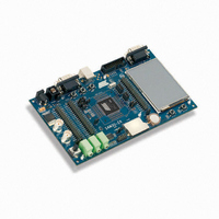
KIT EVAL FOR AT91SAM3U CORTEX
Manufacturer
Atmel
Type
MCUr
Datasheets
1.ATSAM3U-EK.pdf
(2 pages)
2.ATSAM3U-EK.pdf
(61 pages)
3.ATSAM3U-EK.pdf
(1171 pages)
4.ATSAM3U-EK.pdf
(53 pages)
Specifications of ATSAM3U-EK
Contents
Board
Processor To Be Evaluated
SAM3U
Data Bus Width
32 bit
Interface Type
RS-232, USB
Operating Supply Voltage
3 V
Silicon Manufacturer
Atmel
Core Architecture
ARM
Core Sub-architecture
Cortex - M3
Silicon Core Number
SAM3U4E
Silicon Family Name
SAM3U
Kit Contents
Board CD Docs
Rohs Compliant
Yes
For Use With/related Products
AT91SAM3U
Lead Free Status / RoHS Status
Lead free / RoHS Compliant
Available stocks
Company
Part Number
Manufacturer
Quantity
Price
Company:

Part Number:
ATSAM3U-EK
Manufacturer:
Atmel
Quantity:
10


37.8.1
37.8.2
37.9
37.9.1
826
CE-ATA Operation
SAM3U Series
SDIO Data Transfer Type
SDIO Interrupts
Executing an ATA Polling Command
The SD/SDIO Card Register (HSMCI_SDCR) allows selection of the Card Slot and the data bus
width.
The SD/SDIO Card bus allows dynamic configuration of the number of data lines. After power
up, by default, the SD/SDIO Card uses only DAT0 for data transfer. After initialization, the host
can change the bus width (number of active data lines).
SDIO cards may transfer data in either a multi-byte (1 to 512 bytes) or an optional block format
(1 to 511 blocks), while the SD memory cards are fixed in the block transfer mode. The TRTYP
field in the HSMCI Command Register (HSMCI_CMDR) allows to choose between SDIO Byte or
SDIO Block transfer.
The number of bytes/blocks to transfer is set through the BCNT field in the HSMCI Block Regis-
ter (HSMCI_BLKR). In SDIO Block mode, the field BLKLEN must be set to the data block size
while this field is not used in SDIO Byte mode.
An SDIO Card can have multiple I/O or combined I/O and memory (called Combo Card). Within
a multi-function SDIO or a Combo card, there are multiple devices (I/O and memory) that share
access to the SD bus. In order to allow the sharing of access to the host among multiple devices,
SDIO and combo cards can implement the optional concept of suspend/resume (Refer to the
SDIO Specification for more details). To send a suspend or a resume command, the host must
set the SDIO Special Command field (IOSPCMD) in the HSMCI Command Register.
Each function within an SDIO or Combo card may implement interrupts (Refer to the SDIO
Specification for more details). In order to allow the SDIO card to interrupt the host, an interrupt
function is added to a pin on the DAT[1] line to signal the card’s interrupt to the host. An SDIO
interrupt on each slot can be enabled through the HSMCI Interrupt Enable Register. The SDIO
interrupt is sampled regardless of the currently selected slot.
CE-ATA maps the streamlined ATA command set onto the MMC interface. The ATA task file is
mapped onto MMC register space.
CE-ATA utilizes five MMC commands:
CE-ATA utilizes the same MMC command sequences for initialization as traditional MMC
devices.
• GO_IDLE_STATE (CMD0): used for hard reset.
• STOP_TRANSMISSION (CMD12): causes the ATA command currently executing to be
• FAST_IO (CMD39): Used for single register access to the ATA taskfile registers, 8 bit access
• RW_MULTIPLE_REGISTERS (CMD60): used to issue an ATA command or to access the
• RW_MULTIPLE_BLOCK (CMD61): used to transfer data for an ATA command.
1. Issue READ_DMA_EXT with RW_MULTIPLE_REGISTER (CMD60) for 8kB of DATA.
2. Read the ATA status register until DRQ is set.
aborted.
only.
control/status registers.
6430D–ATARM–25-Mar-11
Related parts for ATSAM3U-EK
Image
Part Number
Description
Manufacturer
Datasheet
Request
R

Part Number:
Description:
AT91 ARM Thumb-based Microcontrollers
Manufacturer:
ATMEL [ATMEL Corporation]
Datasheet:

Part Number:
Description:
DEV KIT FOR AVR/AVR32
Manufacturer:
Atmel
Datasheet:

Part Number:
Description:
INTERVAL AND WIPE/WASH WIPER CONTROL IC WITH DELAY
Manufacturer:
ATMEL Corporation
Datasheet:
Part Number:
Description:
Low-Voltage Voice-Switched IC for Hands-Free Operation
Manufacturer:
ATMEL Corporation
Datasheet:
Part Number:
Description:
MONOLITHIC INTEGRATED FEATUREPHONE CIRCUIT
Manufacturer:
ATMEL Corporation
Datasheet:
Part Number:
Description:
AM-FM Receiver IC U4255BM-M
Manufacturer:
ATMEL Corporation
Datasheet:
Part Number:
Description:
Monolithic Integrated Feature Phone Circuit
Manufacturer:
ATMEL Corporation
Datasheet:
Part Number:
Description:
Multistandard Video-IF and Quasi Parallel Sound Processing
Manufacturer:
ATMEL Corporation
Datasheet:
Part Number:
Description:
High-performance EE PLD
Manufacturer:
ATMEL Corporation
Datasheet:
Part Number:
Description:
8-bit Flash Microcontroller
Manufacturer:
ATMEL Corporation
Datasheet:
Part Number:
Description:
2-Wire Serial EEPROM
Manufacturer:
ATMEL Corporation
Datasheet: