ATSAM3U-EK Atmel, ATSAM3U-EK Datasheet - Page 670
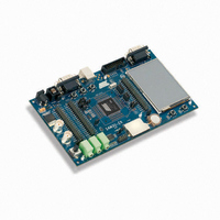
ATSAM3U-EK
Manufacturer Part Number
ATSAM3U-EK
Description
KIT EVAL FOR AT91SAM3U CORTEX
Manufacturer
Atmel
Type
MCUr
Datasheets
1.ATSAM3U-EK.pdf
(2 pages)
2.ATSAM3U-EK.pdf
(61 pages)
3.ATSAM3U-EK.pdf
(1171 pages)
4.ATSAM3U-EK.pdf
(53 pages)
Specifications of ATSAM3U-EK
Contents
Board
Processor To Be Evaluated
SAM3U
Data Bus Width
32 bit
Interface Type
RS-232, USB
Operating Supply Voltage
3 V
Silicon Manufacturer
Atmel
Core Architecture
ARM
Core Sub-architecture
Cortex - M3
Silicon Core Number
SAM3U4E
Silicon Family Name
SAM3U
Kit Contents
Board CD Docs
Rohs Compliant
Yes
For Use With/related Products
AT91SAM3U
Lead Free Status / RoHS Status
Lead free / RoHS Compliant
Available stocks
Company
Part Number
Manufacturer
Quantity
Price
Company:

Part Number:
ATSAM3U-EK
Manufacturer:
Atmel
Quantity:
10


34.4.3
34.4.3.1
34.4.3.2
Figure 34-9. Character Transmission
34.4.3.3
670
SAM3U Series
Transmitter
Transmitter Reset, Enable and Disable
Transmit Format
Transmitter Control
Baud Rate
Example: Parity enabled
UTXD
Clock
After device reset, the UART transmitter is disabled and it must be enabled before being used.
The transmitter is enabled by writing the control register UART_CR with the bit TXEN at 1. From
this command, the transmitter waits for a character to be written in the Transmit Holding Register
(UART_THR) before actually starting the transmission.
The programmer can disable the transmitter by writing UART_CR with the bit TXDIS at 1. If the
transmitter is not operating, it is immediately stopped. However, if a character is being pro-
cessed into the Shift Register and/or a character has been written in the Transmit Holding
Register, the characters are completed before the transmitter is actually stopped.
The programmer can also put the transmitter in its reset state by writing the UART_CR with the
bit RSTTX at 1. This immediately stops the transmitter, whether or not it is processing
characters.
The UART transmitter drives the pin UTXD at the baud rate clock speed. The line is driven
depending on the format defined in the Mode Register and the data stored in the Shift Register.
One start bit at level 0, then the 8 data bits, from the lowest to the highest bit, one optional parity
bit and one stop bit at 1 are consecutively shifted out as shown in the following figure. The field
PARE in the mode register UART_MR defines whether or not a parity bit is shifted out. When a
parity bit is enabled, it can be selected between an odd parity, an even parity, or a fixed space or
mark bit.
When the transmitter is enabled, the bit TXRDY (Transmitter Ready) is set in the status register
UART_SR. The transmission starts when the programmer writes in the Transmit Holding Regis-
ter (UART_THR), and after the written character is transferred from UART_THR to the Shift
Register. The TXRDY bit remains high until a second character is written in UART_THR. As
soon as the first character is completed, the last character written in UART_THR is transferred
into the shift register and TXRDY rises again, showing that the holding register is empty.
When both the Shift Register and UART_THR are empty, i.e., all the characters written in
UART_THR have been processed, the TXEMPTY bit rises after the last stop bit has been
completed.
Start
Bit
D0
D1
D2
D3
D4
D5
D6
D7
Parity
Bit
Stop
Bit
6430D–ATARM–25-Mar-11
Related parts for ATSAM3U-EK
Image
Part Number
Description
Manufacturer
Datasheet
Request
R

Part Number:
Description:
AT91 ARM Thumb-based Microcontrollers
Manufacturer:
ATMEL [ATMEL Corporation]
Datasheet:

Part Number:
Description:
DEV KIT FOR AVR/AVR32
Manufacturer:
Atmel
Datasheet:

Part Number:
Description:
INTERVAL AND WIPE/WASH WIPER CONTROL IC WITH DELAY
Manufacturer:
ATMEL Corporation
Datasheet:
Part Number:
Description:
Low-Voltage Voice-Switched IC for Hands-Free Operation
Manufacturer:
ATMEL Corporation
Datasheet:
Part Number:
Description:
MONOLITHIC INTEGRATED FEATUREPHONE CIRCUIT
Manufacturer:
ATMEL Corporation
Datasheet:
Part Number:
Description:
AM-FM Receiver IC U4255BM-M
Manufacturer:
ATMEL Corporation
Datasheet:
Part Number:
Description:
Monolithic Integrated Feature Phone Circuit
Manufacturer:
ATMEL Corporation
Datasheet:
Part Number:
Description:
Multistandard Video-IF and Quasi Parallel Sound Processing
Manufacturer:
ATMEL Corporation
Datasheet:
Part Number:
Description:
High-performance EE PLD
Manufacturer:
ATMEL Corporation
Datasheet:
Part Number:
Description:
8-bit Flash Microcontroller
Manufacturer:
ATMEL Corporation
Datasheet:
Part Number:
Description:
2-Wire Serial EEPROM
Manufacturer:
ATMEL Corporation
Datasheet: