ATSAM3U-EK Atmel, ATSAM3U-EK Datasheet - Page 776
ATSAM3U-EK
Manufacturer Part Number
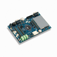
ATSAM3U-EK
Description
KIT EVAL FOR AT91SAM3U CORTEX
Manufacturer
Atmel
Type
MCUr
Datasheets
1.ATSAM3U-EK.pdf
(2 pages)
2.ATSAM3U-EK.pdf
(61 pages)
3.ATSAM3U-EK.pdf
(1171 pages)
4.ATSAM3U-EK.pdf
(53 pages)
Specifications of ATSAM3U-EK
Contents
Board
Processor To Be Evaluated
SAM3U
Data Bus Width
32 bit
Interface Type
RS-232, USB
Operating Supply Voltage
3 V
Silicon Manufacturer
Atmel
Core Architecture
ARM
Core Sub-architecture
Cortex - M3
Silicon Core Number
SAM3U4E
Silicon Family Name
SAM3U
Kit Contents
Board CD Docs
Rohs Compliant
Yes
For Use With/related Products
AT91SAM3U
Lead Free Status / RoHS Status
Lead free / RoHS Compliant
Available stocks
Company
Part Number
Manufacturer
Quantity
Price
Company:

Part Number:
ATSAM3U-EK
Manufacturer:
Atmel
Quantity:
10


36.6.14.5
776
776
SAM3U Series
SAM3U Series
Speed Measurement
In parallel, the number of edges are accumulated on timer/counter channel 0 and can be read on
the TC_CV0 register.
Therefore, the accurate position can be read on both TC_CV registers and concatenated to form
a 32-bit word.
The timer/counter channel 0 is cleared for each increment of IDX count value.
Depending on the quadrature signals, the direction is decoded and allows to count up or down in
timer/counter channels 0 and 1. The direction status is reported on TC_QISR register.
When SPEEDEN is set in TC_BMR register, the speed measure is enabled on channel 0.
A time base must be defined on channel 2 by writing the TC_RC2 period register. Channel 2
must be configured in waveform mode (WAVE bit field set) in TC_CMR2 register. WAVSEL bit
field must be defined with 0x10 to clear the counter by comparison and matching with TC_RC
value. ACPC field must be defined at 0x11 to toggle TIOA output.
This time base is automatically fed back to TIOA of channel 0 when QDEN and SPEEDEN are
set.
Channel 0 must be configured in capture mode (WAVE = 0 in TC_CMR0). ABETRG bit field of
TC_CMR0 must be configured at 1 to get TIOA as a trigger for this channel.
EDGTRG can be set to 0x01, to clear the counter on a rising edge of the TIOA signal and LDRA
field must be set accordingly to 0x01, to load TC_RA0 at the same time as the counter is cleared
(LDRB must be set to 0x01). As a consequence, at the end of each time base period the differ-
entiation required for the speed calculation is performed.
The process must be started by configuring the TC_CR register with CLKEN and SWTRG.
The speed can be read on TC_RA0 register in TC_CMR0.
Channel 1 can still be used to count the number of revolutions of the motor.
6430D–ATARM–25-Mar-11
6430D–ATARM–25-Mar-11
Related parts for ATSAM3U-EK
Image
Part Number
Description
Manufacturer
Datasheet
Request
R

Part Number:
Description:
AT91 ARM Thumb-based Microcontrollers
Manufacturer:
ATMEL [ATMEL Corporation]
Datasheet:

Part Number:
Description:
DEV KIT FOR AVR/AVR32
Manufacturer:
Atmel
Datasheet:

Part Number:
Description:
INTERVAL AND WIPE/WASH WIPER CONTROL IC WITH DELAY
Manufacturer:
ATMEL Corporation
Datasheet:
Part Number:
Description:
Low-Voltage Voice-Switched IC for Hands-Free Operation
Manufacturer:
ATMEL Corporation
Datasheet:
Part Number:
Description:
MONOLITHIC INTEGRATED FEATUREPHONE CIRCUIT
Manufacturer:
ATMEL Corporation
Datasheet:
Part Number:
Description:
AM-FM Receiver IC U4255BM-M
Manufacturer:
ATMEL Corporation
Datasheet:
Part Number:
Description:
Monolithic Integrated Feature Phone Circuit
Manufacturer:
ATMEL Corporation
Datasheet:
Part Number:
Description:
Multistandard Video-IF and Quasi Parallel Sound Processing
Manufacturer:
ATMEL Corporation
Datasheet:
Part Number:
Description:
High-performance EE PLD
Manufacturer:
ATMEL Corporation
Datasheet:
Part Number:
Description:
8-bit Flash Microcontroller
Manufacturer:
ATMEL Corporation
Datasheet:
Part Number:
Description:
2-Wire Serial EEPROM
Manufacturer:
ATMEL Corporation
Datasheet: