ATSAM3U-EK Atmel, ATSAM3U-EK Datasheet - Page 466
ATSAM3U-EK
Manufacturer Part Number
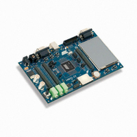
ATSAM3U-EK
Description
KIT EVAL FOR AT91SAM3U CORTEX
Manufacturer
Atmel
Type
MCUr
Datasheets
1.ATSAM3U-EK.pdf
(2 pages)
2.ATSAM3U-EK.pdf
(61 pages)
3.ATSAM3U-EK.pdf
(1171 pages)
4.ATSAM3U-EK.pdf
(53 pages)
Specifications of ATSAM3U-EK
Contents
Board
Processor To Be Evaluated
SAM3U
Data Bus Width
32 bit
Interface Type
RS-232, USB
Operating Supply Voltage
3 V
Silicon Manufacturer
Atmel
Core Architecture
ARM
Core Sub-architecture
Cortex - M3
Silicon Core Number
SAM3U4E
Silicon Family Name
SAM3U
Kit Contents
Board CD Docs
Rohs Compliant
Yes
For Use With/related Products
AT91SAM3U
Lead Free Status / RoHS Status
Lead free / RoHS Compliant
Available stocks
Company
Part Number
Manufacturer
Quantity
Price
Company:

Part Number:
ATSAM3U-EK
Manufacturer:
Atmel
Quantity:
10


28.10 Clock Failure Detector
The clock failure detector allows to monitor the 3 to 20 MHz Crystal Oscillator and to detect an
eventual defect of this oscillator (for example if the crystal is disconnected).
The clock failure detector can be enabled or disabled by means of the CFDEN bit in the PMC
Clock Generator Main Oscillator Register (CKGR_MOR). After reset, the detector is disabled.
However, if the 3 to 20 MHz Crystal Oscillator is disabled, the clock failure detector is disabled
too.
A failure is detected by means of a counter incrementing on the 3 to 20 MHzCrystal oscillator or
Ceramic Resonator-based oscillator clock edge and timing logic clocked on the slow clock RC
oscillator controlling the counter. The counter is cleared when the slow clock RC oscillator signal
is low and enabled when the slow clock RC oscillator is high. Thus the failure detection time is 1
slow clock RC oscillator clock period. If, during the high level period of slow clock RC oscillator,
less than 8 fast crystal clock periods have been counted, then a failure is declared.
If a failure of the 3 to 20 MHz Crystal Oscillator clock is detected, the CFDEV flag is set in the
PMC Status Register (PMC_SR), and can generate an interrupt if it is not masked. The interrupt
remains active until a read operation in the PMC_SR register. The user can know the status of
the clock failure detector at any time by reading the CFDS bit in the PMC_SR register.
If the 3 to 20 MHz Crystal Oscillator clock is selected as the source clock of MAINCK (MOSC-
SEL = 1), and if the Master Clock Source is PLLACK or UPLLCK (CSS = 2 or 3), then a clock
failure detection switches automatically the Master Clock on MAINCK. Then whatever the PMC
configuration is, a clock failure detection switches automatically MAINCK on the 4/8/12 MHz
Fast RC Oscillator clock. If the Fast RC Oscillator is disabled when a clock failure detection
occurs, it is automatically re-enabled by the clock failure detection mechanism.
A clock failure detection activates a fault output that is connected to the Pulse Width Modulator
(PWM) Controller. With this connection, the PWM controller is able to force its outputs and to
protect the driven device, if a clock failure is detected. This fault output remains active until the
defect is detected and until it is not cleared by the bit FOCLR in the PMC Fault Output Clear
Register (PMC_FOCR).
It takes 2 slow clock RC oscillator cycles to detect and switch from the 3 to 20 MHz Crystal or
Ceramic Resonator-based oscillator to the 4/8/12 MHz Fast RC Oscillator if the Master Clock
source is Main Clock, or 3 slow clock RC oscillator cycles if the Master Clock source is PLL.
The user can know the status of the fault output at any time by reading the FOS bit in the
PMC_SR register.
SAM3U Series
466
6430D–ATARM–25-Mar-11
Related parts for ATSAM3U-EK
Image
Part Number
Description
Manufacturer
Datasheet
Request
R

Part Number:
Description:
AT91 ARM Thumb-based Microcontrollers
Manufacturer:
ATMEL [ATMEL Corporation]
Datasheet:

Part Number:
Description:
DEV KIT FOR AVR/AVR32
Manufacturer:
Atmel
Datasheet:

Part Number:
Description:
INTERVAL AND WIPE/WASH WIPER CONTROL IC WITH DELAY
Manufacturer:
ATMEL Corporation
Datasheet:
Part Number:
Description:
Low-Voltage Voice-Switched IC for Hands-Free Operation
Manufacturer:
ATMEL Corporation
Datasheet:
Part Number:
Description:
MONOLITHIC INTEGRATED FEATUREPHONE CIRCUIT
Manufacturer:
ATMEL Corporation
Datasheet:
Part Number:
Description:
AM-FM Receiver IC U4255BM-M
Manufacturer:
ATMEL Corporation
Datasheet:
Part Number:
Description:
Monolithic Integrated Feature Phone Circuit
Manufacturer:
ATMEL Corporation
Datasheet:
Part Number:
Description:
Multistandard Video-IF and Quasi Parallel Sound Processing
Manufacturer:
ATMEL Corporation
Datasheet:
Part Number:
Description:
High-performance EE PLD
Manufacturer:
ATMEL Corporation
Datasheet:
Part Number:
Description:
8-bit Flash Microcontroller
Manufacturer:
ATMEL Corporation
Datasheet:
Part Number:
Description:
2-Wire Serial EEPROM
Manufacturer:
ATMEL Corporation
Datasheet: