ATSAM3U-EK Atmel, ATSAM3U-EK Datasheet - Page 285
ATSAM3U-EK
Manufacturer Part Number
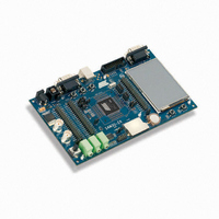
ATSAM3U-EK
Description
KIT EVAL FOR AT91SAM3U CORTEX
Manufacturer
Atmel
Type
MCUr
Datasheets
1.ATSAM3U-EK.pdf
(2 pages)
2.ATSAM3U-EK.pdf
(61 pages)
3.ATSAM3U-EK.pdf
(1171 pages)
4.ATSAM3U-EK.pdf
(53 pages)
Specifications of ATSAM3U-EK
Contents
Board
Processor To Be Evaluated
SAM3U
Data Bus Width
32 bit
Interface Type
RS-232, USB
Operating Supply Voltage
3 V
Silicon Manufacturer
Atmel
Core Architecture
ARM
Core Sub-architecture
Cortex - M3
Silicon Core Number
SAM3U4E
Silicon Family Name
SAM3U
Kit Contents
Board CD Docs
Rohs Compliant
Yes
For Use With/related Products
AT91SAM3U
Lead Free Status / RoHS Status
Lead free / RoHS Compliant
Available stocks
Company
Part Number
Manufacturer
Quantity
Price
Company:

Part Number:
ATSAM3U-EK
Manufacturer:
Atmel
Quantity:
10


19.3
19.3.1
6430D–ATARM–25-Mar-11
Supply Controller Functional Description
Supply Controller Overview
The device can be divided into two power supply areas:
The Supply Controller (SUPC) controls the supply voltage of the core power supply. The SUPC
intervenes when the VDDUTMI power supply rises (when the system is starting) or when the
Backup Low Power Mode is entered.
The SUPC also integrates the Slow Clock generator which is based on a 32 kHz crystal oscilla-
tor and an embedded 32 kHz RC oscillator. The Slow Clock defaults to the RC oscillator, but the
software can enable the crystal oscillator and select it as the Slow Clock source.
The Supply Controller and the VDDUTMI power supply have a reset circuitry based on the
NRSTB pin and a zero-power power-on reset cell. The zero-power power-on reset allows the
SUPC to start properly as soon as the VDDUTMI voltage becomes valid. The NRSTB pin allows
to reset the system from outside.
At startup of the system, once the backup voltage VDDUTMI is valid and the reset pin NRSTB is
not driven low and the embedded 32 kHz RC oscillator is stabilized, the SUPC starts up the core
by sequentially enabling the internal Voltage Regulator, waiting that the core voltage VDDCORE
is valid, then releasing the reset signal of the core “vddcore_nreset” signal.
Once the system has started, the user can program a supply monitor and/or a brownout detec-
tor. If the supply monitor detects a voltage on VDDUTMI that is too low, the SUPC can assert the
reset signal of the core “vddcore_nreset” signal until VDDUTMI is valid. Likewise, if the brownout
detector detects a core voltage VDDCORE that is too low, the SUPC can assert the reset signal
“vddcore_nreset” until VDDCORE is valid.
When the Backup Low Power Mode is entered, the SUPC sequentially asserts the reset signal
of the core power supply “vddcore_nreset” and disables the voltage regulator, in order to supply
only the VDDUTMI power supply. In this mode the current consumption is reduced to a few
microamps for Backup part retention. Exit from this mode is possible on multiple wake-up
sources including an event on FWUP pin or WKUP pins, or a Clock alarm. To exit this mode, the
SUPC operates in the same way as system startup.
• The Backup VDDBU Power Supply: including the Supply Controller, a part of the Reset
• The Core Power Supply: including the other part of the Reset Controller, the Brownout
Controller, the Slow Clock switch, the General Purpose Backup Registers, the Supply
Monitor and the Clock which includes the Real Time Timer and the Real Time Clock
Detector, the Processor, the SRAM memory, the FLASH memory and the Peripherals
SAM3U Series
285
Related parts for ATSAM3U-EK
Image
Part Number
Description
Manufacturer
Datasheet
Request
R

Part Number:
Description:
AT91 ARM Thumb-based Microcontrollers
Manufacturer:
ATMEL [ATMEL Corporation]
Datasheet:

Part Number:
Description:
DEV KIT FOR AVR/AVR32
Manufacturer:
Atmel
Datasheet:

Part Number:
Description:
INTERVAL AND WIPE/WASH WIPER CONTROL IC WITH DELAY
Manufacturer:
ATMEL Corporation
Datasheet:
Part Number:
Description:
Low-Voltage Voice-Switched IC for Hands-Free Operation
Manufacturer:
ATMEL Corporation
Datasheet:
Part Number:
Description:
MONOLITHIC INTEGRATED FEATUREPHONE CIRCUIT
Manufacturer:
ATMEL Corporation
Datasheet:
Part Number:
Description:
AM-FM Receiver IC U4255BM-M
Manufacturer:
ATMEL Corporation
Datasheet:
Part Number:
Description:
Monolithic Integrated Feature Phone Circuit
Manufacturer:
ATMEL Corporation
Datasheet:
Part Number:
Description:
Multistandard Video-IF and Quasi Parallel Sound Processing
Manufacturer:
ATMEL Corporation
Datasheet:
Part Number:
Description:
High-performance EE PLD
Manufacturer:
ATMEL Corporation
Datasheet:
Part Number:
Description:
8-bit Flash Microcontroller
Manufacturer:
ATMEL Corporation
Datasheet:
Part Number:
Description:
2-Wire Serial EEPROM
Manufacturer:
ATMEL Corporation
Datasheet: