ATSAM3U-EK Atmel, ATSAM3U-EK Datasheet - Page 510
ATSAM3U-EK
Manufacturer Part Number
ATSAM3U-EK
Description
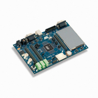
KIT EVAL FOR AT91SAM3U CORTEX
Manufacturer
Atmel
Type
MCUr
Datasheets
1.ATSAM3U-EK.pdf
(2 pages)
2.ATSAM3U-EK.pdf
(61 pages)
3.ATSAM3U-EK.pdf
(1171 pages)
4.ATSAM3U-EK.pdf
(53 pages)
Specifications of ATSAM3U-EK
Contents
Board
Processor To Be Evaluated
SAM3U
Data Bus Width
32 bit
Interface Type
RS-232, USB
Operating Supply Voltage
3 V
Silicon Manufacturer
Atmel
Core Architecture
ARM
Core Sub-architecture
Cortex - M3
Silicon Core Number
SAM3U4E
Silicon Family Name
SAM3U
Kit Contents
Board CD Docs
Rohs Compliant
Yes
For Use With/related Products
AT91SAM3U
Lead Free Status / RoHS Status
Lead free / RoHS Compliant
Available stocks
Company
Part Number
Manufacturer
Quantity
Price
Company:

Part Number:
ATSAM3U-EK
Manufacturer:
Atmel
Quantity:
10


Figure 30-5. Input Glitch Filter Timing
Figure 30-6. Input Debouncing Filter Timing
30.5.10
510
510
Divided Slow Clock
if PIO_IFSR = 0
if PIO_IFSR = 1
PIO_PDSR
PIO_PDSR
Pin Level
SAM3U Series
SAM3U Series
if PIO_IFSR = 0
if PIO_IFSR = 1
Input Edge/Level Interrupt
PIO_PDSR
PIO_PDSR
Pin Level
MCK
up to 2 cycles Tmck
not be taken into account, depending on the precise timing of its occurrence. Thus for a pulse to
be visible it must exceed 1 Selected Clock cycle, whereas for a glitch to be reliably filtered out,
its duration must not exceed 1/2 Selected Clock cycle.
The filters also introduce some latencies, this is illustrated in
The glitch filters are controlled by the register set: PIO_IFER (Input Filter Enable Register),
PIO_IFDR (Input Filter Disable Register) and PIO_IFSR (Input Filter Status Register). Writing
PIO_IFER and PIO_IFDR respectively sets and clears bits in PIO_IFSR. This last register
enables the glitch filter on the I/O lines.
When the glitch and/or debouncing filter is enabled, it does not modify the behavior of the inputs
on the peripherals. It acts only on the value read in PIO_PDSR and on the input change interrupt
detection. The glitch and debouncing filters require that the PIO Controller clock is enabled.
The PIO Controller can be programmed to generate an interrupt when it detects an edge or a
level on an I/O line. The Input Edge/Level Interrupt is controlled by writing PIO_IER (Interrupt
Enable Register) and PIO_IDR (Interrupt Disable Register), which respectively enable and dis-
able the input change interrupt by setting and clearing the corresponding bit in PIO_IMR
(Interrupt Mask Register). As Input change detection is possible only by comparing two succes-
1 cycle
1 cycle
up to 2 cycles Tmck
PIO_IFCSR = 1
PIO_IFCSR = 0
up to 1.5 cycles Tdiv_slclk
1 cycle Tdiv_slclk
up to 1.5 cycles
1 cycle
up to 2.5 cycles
up to 2 cycles Tmck
2 cycles
Figure 30-5
up to 1.5 cycles Tdiv_slclk
1 cycle Tdiv_slclk
up to 2 cycles
and
6430D–ATARM–25-Mar-11
6430D–ATARM–25-Mar-11
1 cycle
1 cycle
Figure
up to 2 cycles Tmck
30-6.
Related parts for ATSAM3U-EK
Image
Part Number
Description
Manufacturer
Datasheet
Request
R

Part Number:
Description:
AT91 ARM Thumb-based Microcontrollers
Manufacturer:
ATMEL [ATMEL Corporation]
Datasheet:

Part Number:
Description:
DEV KIT FOR AVR/AVR32
Manufacturer:
Atmel
Datasheet:

Part Number:
Description:
INTERVAL AND WIPE/WASH WIPER CONTROL IC WITH DELAY
Manufacturer:
ATMEL Corporation
Datasheet:
Part Number:
Description:
Low-Voltage Voice-Switched IC for Hands-Free Operation
Manufacturer:
ATMEL Corporation
Datasheet:
Part Number:
Description:
MONOLITHIC INTEGRATED FEATUREPHONE CIRCUIT
Manufacturer:
ATMEL Corporation
Datasheet:
Part Number:
Description:
AM-FM Receiver IC U4255BM-M
Manufacturer:
ATMEL Corporation
Datasheet:
Part Number:
Description:
Monolithic Integrated Feature Phone Circuit
Manufacturer:
ATMEL Corporation
Datasheet:
Part Number:
Description:
Multistandard Video-IF and Quasi Parallel Sound Processing
Manufacturer:
ATMEL Corporation
Datasheet:
Part Number:
Description:
High-performance EE PLD
Manufacturer:
ATMEL Corporation
Datasheet:
Part Number:
Description:
8-bit Flash Microcontroller
Manufacturer:
ATMEL Corporation
Datasheet:
Part Number:
Description:
2-Wire Serial EEPROM
Manufacturer:
ATMEL Corporation
Datasheet: