ATSAM3U-EK Atmel, ATSAM3U-EK Datasheet - Page 233
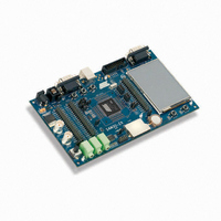
ATSAM3U-EK
Manufacturer Part Number
ATSAM3U-EK
Description
KIT EVAL FOR AT91SAM3U CORTEX
Manufacturer
Atmel
Type
MCUr
Datasheets
1.ATSAM3U-EK.pdf
(2 pages)
2.ATSAM3U-EK.pdf
(61 pages)
3.ATSAM3U-EK.pdf
(1171 pages)
4.ATSAM3U-EK.pdf
(53 pages)
Specifications of ATSAM3U-EK
Contents
Board
Processor To Be Evaluated
SAM3U
Data Bus Width
32 bit
Interface Type
RS-232, USB
Operating Supply Voltage
3 V
Silicon Manufacturer
Atmel
Core Architecture
ARM
Core Sub-architecture
Cortex - M3
Silicon Core Number
SAM3U4E
Silicon Family Name
SAM3U
Kit Contents
Board CD Docs
Rohs Compliant
Yes
For Use With/related Products
AT91SAM3U
Lead Free Status / RoHS Status
Lead free / RoHS Compliant
Available stocks
Company
Part Number
Manufacturer
Quantity
Price
Company:

Part Number:
ATSAM3U-EK
Manufacturer:
Atmel
Quantity:
10


14.3
14.4
14.4.1
6430D–ATARM–25-Mar-11
Debug and Test Pin Description
Functional Description
Test Pin
Figure 14-3. Application Test Environment Example
Table 14-1.
Note:
One dedicated pin, TST, is used to define the device operating mode. When this pin is at low
level during power-up, the device is in normal operating mode. When at high level, the device is
in test mode or FFPI mode. The TST pin integrates a permanent pull-down resistor of about
15 kΩ, so that it can be left unconnected for normal operation. Note that when setting the TST pin
Signal Name
NRST
TST
TCK/SWCLK
TDI
TDO/TRACESWO
TMS/SWDIO
JTAGSEL
1. TDO pin is set in input mode when the Cortex-M3 Core is not in debug mode. Thus an external
pull-up (100 kΩ) must be added to avoid current consumption due to floating input.
Debug and Test Signal List
SAM3-based Application Board In Test
Connector
JTAG
Probe
JTAG
Function
Microcontroller Reset
Test Select
Test Clock/Serial Wire Clock
Test Data In
Test Data Out/Trace Asynchronous
Data Out
Test Mode Select/Serial Wire
Input/Output
JTAG Selection
SAM3
Chip n
SWD/JTAG
Reset/Test
Test Adaptor
Chip 2
Chip 1
Tester
Input/Output
Output
Type
Input
Input
Input
Input
Input
SAM3U Series
(1)
Active Level
High
Low
233
Related parts for ATSAM3U-EK
Image
Part Number
Description
Manufacturer
Datasheet
Request
R

Part Number:
Description:
AT91 ARM Thumb-based Microcontrollers
Manufacturer:
ATMEL [ATMEL Corporation]
Datasheet:

Part Number:
Description:
DEV KIT FOR AVR/AVR32
Manufacturer:
Atmel
Datasheet:

Part Number:
Description:
INTERVAL AND WIPE/WASH WIPER CONTROL IC WITH DELAY
Manufacturer:
ATMEL Corporation
Datasheet:
Part Number:
Description:
Low-Voltage Voice-Switched IC for Hands-Free Operation
Manufacturer:
ATMEL Corporation
Datasheet:
Part Number:
Description:
MONOLITHIC INTEGRATED FEATUREPHONE CIRCUIT
Manufacturer:
ATMEL Corporation
Datasheet:
Part Number:
Description:
AM-FM Receiver IC U4255BM-M
Manufacturer:
ATMEL Corporation
Datasheet:
Part Number:
Description:
Monolithic Integrated Feature Phone Circuit
Manufacturer:
ATMEL Corporation
Datasheet:
Part Number:
Description:
Multistandard Video-IF and Quasi Parallel Sound Processing
Manufacturer:
ATMEL Corporation
Datasheet:
Part Number:
Description:
High-performance EE PLD
Manufacturer:
ATMEL Corporation
Datasheet:
Part Number:
Description:
8-bit Flash Microcontroller
Manufacturer:
ATMEL Corporation
Datasheet:
Part Number:
Description:
2-Wire Serial EEPROM
Manufacturer:
ATMEL Corporation
Datasheet: