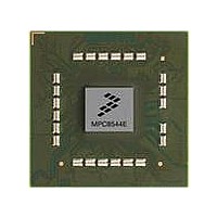
MPC8544DS Freescale Semiconductor, MPC8544DS Datasheet - Page 451

MPC8544DS
Manufacturer Part Number
MPC8544DS
Description
BOARD DEVELOPMENT SYSTEM 8544
Manufacturer
Freescale Semiconductor
Series
PowerQUICC III™r
Type
MPUr
Datasheets
1.MPC8544VTALF.pdf
(117 pages)
2.MPC8544VTALF.pdf
(2 pages)
3.MPC8544VTALF.pdf
(1340 pages)
4.MPC8544DS.pdf
(2 pages)
Specifications of MPC8544DS
Contents
Board
Processor To Be Evaluated
MPC8544E
Data Bus Width
32 bit
Interface Type
Ethernet, I2C
Operating Supply Voltage
- 0.3 V to + 1.1 V
Leaded Process Compatible
Yes
Peak Reflow Compatible (260 C)
Yes
Rohs Compliant
Yes
For Use With/related Products
MPC8544
For Use With
PPC8544EVTANG - EVAL MPC8544 783FCPBGA
Lead Free Status / RoHS Status
Lead free / RoHS Compliant
- MPC8544VTALF PDF datasheet
- MPC8544VTALF PDF datasheet #2
- MPC8544VTALF PDF datasheet #3
- MPC8544DS PDF datasheet #4
- Current page: 451 of 1340
- Download datasheet (12Mb)
count down to zero and can be used to generate regular periodic interrupts. Each timer has the following
four configuration and control registers:
The timer frequency should be written to the TFRR. (All of the timers operate at this frequency.) Refer to
Section 10.3.2.1, “Timer Frequency Reporting Register (TFRR),”
Timer interrupts are all edge-triggered interrupts. If a timer period expires while a previous interrupt from
the same source is pending or in-service, the subsequent interrupt is lost.
The timer control register (TCR) provides users with the ability to create timers larger than the 31-bit
global timers. The option also exists to change the timer frequency by setting the appropriate fields of the
TCR. See
10.4.8
The PIC unit is reset by a device power-on reset (POR) or by software that sets the GCR[RST] bit. Both
of these actions cause the following:
The GCR[RST] bit is automatically cleared when the reset sequence is complete.
10.5
This section contains initialization and application information for the PIC.
10.5.1
The following sections contain information about programming PIC registers.
Freescale Semiconductor
•
•
•
•
•
•
•
•
•
•
•
•
•
•
•
•
Global timer current count register (GTCCRn)
Global timer base count register (GTBCRn)
Global timer vector-priority register (GTVPRn)
Global timer destination register (GTDRn)
All pending and in-service interrupts are cleared.
All interrupt mask bits are set.
Polarity, sense, external pin, critical interrupt, and activity fields are reset to default values.
PIR, TFRR, TCR, MER, MSR, and MSGR0–3 are cleared.
MSG and timer destination fields are set.
The IPI dispatch registers are cleared.
All timer base count values are reset to zero and count inhibited.
The CTPR[TASKP] is reset to 0xF, thus disabling interrupt delivery to the processor.
The spurious interrupt vector resets to 0xFFFF.
The PMMRs are reset to 0xFFFF.
The PIC defaults to the pass-through mode (GCR[M] = 0).
All other registers remain at their pre-reset programmed values.
Section 10.3.2.6, “Timer Control Register (TCR).”
Initialization/Application Information
Reset of the PIC
Programming Guidelines
MPC8544E PowerQUICC III Integrated Host Processor Family Reference Manual, Rev. 1
for a description of this register.
Programmable Interrupt Controller
10-53
Related parts for MPC8544DS
Image
Part Number
Description
Manufacturer
Datasheet
Request
R
Part Number:
Description:
Manufacturer:
Freescale Semiconductor, Inc
Datasheet:
Part Number:
Description:
Manufacturer:
Freescale Semiconductor, Inc
Datasheet:
Part Number:
Description:
Manufacturer:
Freescale Semiconductor, Inc
Datasheet:
Part Number:
Description:
Manufacturer:
Freescale Semiconductor, Inc
Datasheet:
Part Number:
Description:
Manufacturer:
Freescale Semiconductor, Inc
Datasheet:
Part Number:
Description:
Manufacturer:
Freescale Semiconductor, Inc
Datasheet:
Part Number:
Description:
Manufacturer:
Freescale Semiconductor, Inc
Datasheet:
Part Number:
Description:
Manufacturer:
Freescale Semiconductor, Inc
Datasheet:
Part Number:
Description:
Manufacturer:
Freescale Semiconductor, Inc
Datasheet:
Part Number:
Description:
Manufacturer:
Freescale Semiconductor, Inc
Datasheet:
Part Number:
Description:
Manufacturer:
Freescale Semiconductor, Inc
Datasheet:
Part Number:
Description:
Manufacturer:
Freescale Semiconductor, Inc
Datasheet:
Part Number:
Description:
Manufacturer:
Freescale Semiconductor, Inc
Datasheet:
Part Number:
Description:
Manufacturer:
Freescale Semiconductor, Inc
Datasheet:
Part Number:
Description:
Manufacturer:
Freescale Semiconductor, Inc
Datasheet:


