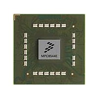
MPC8544DS Freescale Semiconductor, MPC8544DS Datasheet - Page 55

MPC8544DS
Manufacturer Part Number
MPC8544DS
Description
BOARD DEVELOPMENT SYSTEM 8544
Manufacturer
Freescale Semiconductor
Series
PowerQUICC III™r
Type
MPUr
Datasheets
1.MPC8544VTALF.pdf
(117 pages)
2.MPC8544VTALF.pdf
(2 pages)
3.MPC8544VTALF.pdf
(1340 pages)
4.MPC8544DS.pdf
(2 pages)
Specifications of MPC8544DS
Contents
Board
Processor To Be Evaluated
MPC8544E
Data Bus Width
32 bit
Interface Type
Ethernet, I2C
Operating Supply Voltage
- 0.3 V to + 1.1 V
Leaded Process Compatible
Yes
Peak Reflow Compatible (260 C)
Yes
Rohs Compliant
Yes
For Use With/related Products
MPC8544
For Use With
PPC8544EVTANG - EVAL MPC8544 783FCPBGA
Lead Free Status / RoHS Status
Lead free / RoHS Compliant
- MPC8544VTALF PDF datasheet
- MPC8544VTALF PDF datasheet #2
- MPC8544VTALF PDF datasheet #3
- MPC8544DS PDF datasheet #4
- Current page: 55 of 1340
- Download datasheet (12Mb)
Figure
Number
14-48
14-49
14-50
14-51
14-52
14-53
14-54
14-55
14-56
14-57
14-58
14-59
14-60
14-61
14-62
14-63
14-64
14-65
14-66
14-67
14-68
14-69
14-70
14-71
14-72
14-73
14-74
14-75
14-76
14-77
14-78
14-79
14-80
14-81
14-82
14-83
14-84
14-85
14-86
14-87
14-88
Freescale Semiconductor
UPM Read Access Data Sampling...................................................................................... 14-71
Burst Read Access to FPM DRAM Using LOOP (Two Beats Shown).............................. 14-76
SDRAM Read-After-Read Pipelined, Page Hit, CL = 3..................................................... 14-56
SDRAM Write-After-Write Pipelined, Page Hit................................................................. 14-56
SDRAM Read-After-Write Pipelined, Page Hit ................................................................. 14-57
SDRAM MODE-SET Command........................................................................................ 14-57
SDRAM Bank-Staggered Auto-Refresh Timing ................................................................ 14-58
User-Programmable Machine Functional Block Diagram.................................................. 14-59
RAM Array Indexing .......................................................................................................... 14-60
Memory Refresh Timer Request Block Diagram ............................................................... 14-61
UPM Clock Scheme............................................................................................................ 14-64
RAM Array and Signal Generation .................................................................................... 14-64
RAM Word Field Descriptions ........................................................................................... 14-65
LCSn Signal Selection ........................................................................................................ 14-68
LBS Signal Selection .......................................................................................................... 14-68
Effect of LUPWAIT Signal ................................................................................................. 14-72
Single-Beat Read Access to FPM DRAM .......................................................................... 14-74
Single-Beat Write Access to FPM DRAM ......................................................................... 14-75
Refresh Cycle (CBR) to FPM DRAM ................................................................................ 14-77
Exception Cycle .................................................................................................................. 14-78
Multiplexed Address/Data Bus ........................................................................................... 14-79
Local Bus Peripheral Hierarchy.......................................................................................... 14-80
Local Bus Peripheral Hierarchy for Very High Bus Speeds ............................................... 14-81
GPCM Address Timings ..................................................................................................... 14-81
GPCM Data Timings........................................................................................................... 14-82
Interface to Different Port-Size Devices ............................................................................. 14-84
128-Mbyte SDRAM Diagram............................................................................................. 14-88
SDRAM Power-Down Timing............................................................................................ 14-92
SDRAM Self-Refresh Mode Timing .................................................................................. 14-93
Local Bus PLL Operation ................................................................................................... 14-95
Parity Support for SDRAM................................................................................................. 14-96
Interface to ZBT SRAM ..................................................................................................... 14-97
MSC8101 HDI16 Peripheral Registers............................................................................... 14-99
Interface to MSC8101 HDI16........................................................................................... 14-100
Interface to MSC8102 DSI in Asynchronous Mode ......................................................... 14-103
Asynchronous Write to MSC8102 DSI............................................................................. 14-104
Asynchronous Read from MSC8102 DSI......................................................................... 14-105
Interface to MSC8102 DSI in Synchronous Mode ........................................................... 14-106
UPM Synchronization Cycle ............................................................................................ 14-107
Synchronous Single Write to MSC8102 DSI.................................................................... 14-108
Synchronous Single Read from MSC8102 DSI................................................................ 14-109
MPC8544E PowerQUICC III Integrated Host Processor Family Reference Manual, Rev. 1
Figures
Title
Number
Page
lv
Related parts for MPC8544DS
Image
Part Number
Description
Manufacturer
Datasheet
Request
R
Part Number:
Description:
Manufacturer:
Freescale Semiconductor, Inc
Datasheet:
Part Number:
Description:
Manufacturer:
Freescale Semiconductor, Inc
Datasheet:
Part Number:
Description:
Manufacturer:
Freescale Semiconductor, Inc
Datasheet:
Part Number:
Description:
Manufacturer:
Freescale Semiconductor, Inc
Datasheet:
Part Number:
Description:
Manufacturer:
Freescale Semiconductor, Inc
Datasheet:
Part Number:
Description:
Manufacturer:
Freescale Semiconductor, Inc
Datasheet:
Part Number:
Description:
Manufacturer:
Freescale Semiconductor, Inc
Datasheet:
Part Number:
Description:
Manufacturer:
Freescale Semiconductor, Inc
Datasheet:
Part Number:
Description:
Manufacturer:
Freescale Semiconductor, Inc
Datasheet:
Part Number:
Description:
Manufacturer:
Freescale Semiconductor, Inc
Datasheet:
Part Number:
Description:
Manufacturer:
Freescale Semiconductor, Inc
Datasheet:
Part Number:
Description:
Manufacturer:
Freescale Semiconductor, Inc
Datasheet:
Part Number:
Description:
Manufacturer:
Freescale Semiconductor, Inc
Datasheet:
Part Number:
Description:
Manufacturer:
Freescale Semiconductor, Inc
Datasheet:
Part Number:
Description:
Manufacturer:
Freescale Semiconductor, Inc
Datasheet:


