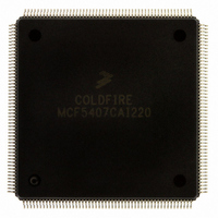
MCF5407CAI220 Freescale Semiconductor, MCF5407CAI220 Datasheet - Page 151

MCF5407CAI220
Manufacturer Part Number
MCF5407CAI220
Description
IC MPU 32B 220MHZ COLDF 208-FQFP
Manufacturer
Freescale Semiconductor
Series
MCF540xr
Specifications of MCF5407CAI220
Core Processor
Coldfire V4
Core Size
32-Bit
Speed
220MHz
Connectivity
EBI/EMI, I²C, UART/USART
Peripherals
DMA, WDT
Number Of I /o
16
Program Memory Type
ROMless
Ram Size
4K x 8
Voltage - Supply (vcc/vdd)
1.65 V ~ 3.6 V
Oscillator Type
External
Operating Temperature
-40°C ~ 85°C
Package / Case
208-FQFP
Processor Series
MCF540x
Core
ColdFire V4
Data Bus Width
32 bit
Program Memory Size
8 KB
Data Ram Size
4 KB
Maximum Clock Frequency
162 MHz
Number Of Programmable I/os
16
Operating Supply Voltage
1.8 V to 3.3 V
Mounting Style
SMD/SMT
3rd Party Development Tools
JLINK-CF-BDM26, EWCF
Cpu Speed
220MHz
Embedded Interface Type
I2C, UART
Digital Ic Case Style
FQFP
No. Of Pins
208
Supply Voltage Range
3.3V
Rohs Compliant
Yes
For Use With
M5407C3 - KIT EVAL FOR MCF5407 W/ETHERNET
Lead Free Status / RoHS Status
Lead free / RoHS Compliant
Eeprom Size
-
Program Memory Size
-
Data Converters
-
Lead Free Status / Rohs Status
Lead free / RoHS Compliant
Available stocks
Company
Part Number
Manufacturer
Quantity
Price
Company:
Part Number:
MCF5407CAI220
Manufacturer:
Freescale
Quantity:
789
Company:
Part Number:
MCF5407CAI220
Manufacturer:
Freescale Semiconductor
Quantity:
10 000
- Current page: 151 of 546
- Download datasheet (7Mb)
; A 8K region was loaded into levels 0 and 1 of the 16-Kbyte instruction cache.
; lock it!
4.12 Cache Operation Summary
This section gives operational details for the cache and presents instruction and data
cache-line state diagrams.
4.12.1 Instruction Cache State Transitions
Because the instruction cache does not support writes, it supports fewer operations than the
data cache. As Figure 4-12 shows, an instruction cache line can be in one of two states, valid
or invalid. Modified state is not supported. Transitions are labeled with a capital letter
indicating the previous state and with a number indicating the specific case listed in
Table 4-6. These numbers correspond to the equivalent operations on data caches,
described in Section 4.12.2, “Data Cache State Transitions.”
Table 4-6 describes the instruction cache state transitions shown in Figure 4-12.
Read miss
Read hit
Write miss
Write hit
II5—ICINVA
II6—CPUSHL & IDPI
II7—CPUSHL & IDPI
Access
lea
subq.l
bne.b
move.l
movec
rts
II1 Read line from memory and update cache;
II2 Not possible
II3 Not possible
II4 Not possible
supply data to processor;
go to valid state.
Table 4-6. Instruction Cache Line State Transitions
Figure 4-12. Instruction Cache Line State Diagram
16(a0),a0
#1,d0
instCacheLoop
#0xa2088800,d0
d0,cacr
Invalid
V = 0
Invalid (V = 0)
Chapter 4. Local Memory
IV5—ICINVA
IV6—CPUSHL & IDPI
;instruction cache
;increment address to next line
;decrement loop counter
;if done, then exit, else continue
;set the instruction cache lock bit
;in the CACR
II1—CPU read miss
Current State
IV1 Read new line from memory and update cache;
IV2 Supply data to processor;
IV3 Not possible
IV4 Not possible
supply data to processor; stay in valid state.
stay in valid state.
V = 1
Valid
Valid (V = 1)
Cache Operation Summary
IV1—CPU read miss
IV2—CPU read hit
IV7—CPUSHL & IDPI
4-27
Related parts for MCF5407CAI220
Image
Part Number
Description
Manufacturer
Datasheet
Request
R
Part Number:
Description:
Mcf5407 Coldfire Integrated Microprocessor User
Manufacturer:
Freescale Semiconductor, Inc
Datasheet:
Part Number:
Description:
Manufacturer:
Freescale Semiconductor, Inc
Datasheet:
Part Number:
Description:
Manufacturer:
Freescale Semiconductor, Inc
Datasheet:
Part Number:
Description:
Manufacturer:
Freescale Semiconductor, Inc
Datasheet:
Part Number:
Description:
Manufacturer:
Freescale Semiconductor, Inc
Datasheet:
Part Number:
Description:
Manufacturer:
Freescale Semiconductor, Inc
Datasheet:
Part Number:
Description:
Manufacturer:
Freescale Semiconductor, Inc
Datasheet:
Part Number:
Description:
Manufacturer:
Freescale Semiconductor, Inc
Datasheet:
Part Number:
Description:
Manufacturer:
Freescale Semiconductor, Inc
Datasheet:
Part Number:
Description:
Manufacturer:
Freescale Semiconductor, Inc
Datasheet:
Part Number:
Description:
Manufacturer:
Freescale Semiconductor, Inc
Datasheet:
Part Number:
Description:
Manufacturer:
Freescale Semiconductor, Inc
Datasheet:
Part Number:
Description:
Manufacturer:
Freescale Semiconductor, Inc
Datasheet:
Part Number:
Description:
Manufacturer:
Freescale Semiconductor, Inc
Datasheet:
Part Number:
Description:
Manufacturer:
Freescale Semiconductor, Inc
Datasheet:


