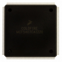
MCF5407CAI220 Freescale Semiconductor, MCF5407CAI220 Datasheet - Page 371

MCF5407CAI220
Manufacturer Part Number
MCF5407CAI220
Description
IC MPU 32B 220MHZ COLDF 208-FQFP
Manufacturer
Freescale Semiconductor
Series
MCF540xr
Specifications of MCF5407CAI220
Core Processor
Coldfire V4
Core Size
32-Bit
Speed
220MHz
Connectivity
EBI/EMI, I²C, UART/USART
Peripherals
DMA, WDT
Number Of I /o
16
Program Memory Type
ROMless
Ram Size
4K x 8
Voltage - Supply (vcc/vdd)
1.65 V ~ 3.6 V
Oscillator Type
External
Operating Temperature
-40°C ~ 85°C
Package / Case
208-FQFP
Processor Series
MCF540x
Core
ColdFire V4
Data Bus Width
32 bit
Program Memory Size
8 KB
Data Ram Size
4 KB
Maximum Clock Frequency
162 MHz
Number Of Programmable I/os
16
Operating Supply Voltage
1.8 V to 3.3 V
Mounting Style
SMD/SMT
3rd Party Development Tools
JLINK-CF-BDM26, EWCF
Cpu Speed
220MHz
Embedded Interface Type
I2C, UART
Digital Ic Case Style
FQFP
No. Of Pins
208
Supply Voltage Range
3.3V
Rohs Compliant
Yes
For Use With
M5407C3 - KIT EVAL FOR MCF5407 W/ETHERNET
Lead Free Status / RoHS Status
Lead free / RoHS Compliant
Eeprom Size
-
Program Memory Size
-
Data Converters
-
Lead Free Status / Rohs Status
Lead free / RoHS Compliant
Available stocks
Company
Part Number
Manufacturer
Quantity
Price
Company:
Part Number:
MCF5407CAI220
Manufacturer:
Freescale
Quantity:
789
Company:
Part Number:
MCF5407CAI220
Manufacturer:
Freescale Semiconductor
Quantity:
10 000
- Current page: 371 of 546
- Download datasheet (7Mb)
14.5.2.2.1 AC ‘97 Low-Power Mode
A general-purpose I/O (GPIO) must be used as an AC ‘97 reset output pin. UART1
monitors the first three time slots of each Tx frame to detect the power-down condition for
the AC ‘97 digital interface. The power-down condition is detected as follows:
Low-power mode can be left through either a warm or cold reset. The CPU performs a
warm reset by setting MODCTL[AWR] for at least 1 µs. This negates RTS, which is used
as the frame sync output in AC ‘97 mode. The CPU performs a cold reset in two steps:
Step 2 is required so UART1 knows when an AC ‘97 cold reset is occurring.
14.5.2.3 Receiver
The receiver is enabled through its UCRn, as described in Section 14.3.10, “UART
Command Registers (UCRn).” Figure 14-34 shows receiver functional timing.
1. The first 3 bits of slot 1 must be set, indicating that the Tx frame and slots 1 and 2
2. Slot 2 holds the address of the power-down register (0x26) in the external AC ‘97
3. Slot 3 contains a 1 in the fourth bit (bit 12/PR4 in power-down register 1), as defined
1. Writes a 0 to whichever GPIO is being used as the active low AC ‘97 reset pin for
2. Writes a 0 to UART1’s MODCTL[ACRB] (bit 7). The CPU sets this bit after writing
are valid.
device.
in the AC ’97 specification.
the minimum time specified in the AC ‘97 specification.
a 1 to the GPIO used for the AC ‘97 reset pin.
Chapter 14. UART Modules
Operation
14-29
Related parts for MCF5407CAI220
Image
Part Number
Description
Manufacturer
Datasheet
Request
R
Part Number:
Description:
Mcf5407 Coldfire Integrated Microprocessor User
Manufacturer:
Freescale Semiconductor, Inc
Datasheet:
Part Number:
Description:
Manufacturer:
Freescale Semiconductor, Inc
Datasheet:
Part Number:
Description:
Manufacturer:
Freescale Semiconductor, Inc
Datasheet:
Part Number:
Description:
Manufacturer:
Freescale Semiconductor, Inc
Datasheet:
Part Number:
Description:
Manufacturer:
Freescale Semiconductor, Inc
Datasheet:
Part Number:
Description:
Manufacturer:
Freescale Semiconductor, Inc
Datasheet:
Part Number:
Description:
Manufacturer:
Freescale Semiconductor, Inc
Datasheet:
Part Number:
Description:
Manufacturer:
Freescale Semiconductor, Inc
Datasheet:
Part Number:
Description:
Manufacturer:
Freescale Semiconductor, Inc
Datasheet:
Part Number:
Description:
Manufacturer:
Freescale Semiconductor, Inc
Datasheet:
Part Number:
Description:
Manufacturer:
Freescale Semiconductor, Inc
Datasheet:
Part Number:
Description:
Manufacturer:
Freescale Semiconductor, Inc
Datasheet:
Part Number:
Description:
Manufacturer:
Freescale Semiconductor, Inc
Datasheet:
Part Number:
Description:
Manufacturer:
Freescale Semiconductor, Inc
Datasheet:
Part Number:
Description:
Manufacturer:
Freescale Semiconductor, Inc
Datasheet:


