MCF5407CAI220 Freescale Semiconductor, MCF5407CAI220 Datasheet - Page 90
MCF5407CAI220
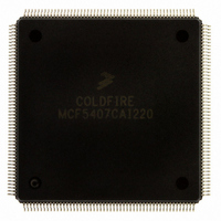
Manufacturer Part Number
MCF5407CAI220
Description
IC MPU 32B 220MHZ COLDF 208-FQFP
Manufacturer
Freescale Semiconductor
Series
MCF540xr
Specifications of MCF5407CAI220
Core Processor
Coldfire V4
Core Size
32-Bit
Speed
220MHz
Connectivity
EBI/EMI, I²C, UART/USART
Peripherals
DMA, WDT
Number Of I /o
16
Program Memory Type
ROMless
Ram Size
4K x 8
Voltage - Supply (vcc/vdd)
1.65 V ~ 3.6 V
Oscillator Type
External
Operating Temperature
-40°C ~ 85°C
Package / Case
208-FQFP
Processor Series
MCF540x
Core
ColdFire V4
Data Bus Width
32 bit
Program Memory Size
8 KB
Data Ram Size
4 KB
Maximum Clock Frequency
162 MHz
Number Of Programmable I/os
16
Operating Supply Voltage
1.8 V to 3.3 V
Mounting Style
SMD/SMT
3rd Party Development Tools
JLINK-CF-BDM26, EWCF
Cpu Speed
220MHz
Embedded Interface Type
I2C, UART
Digital Ic Case Style
FQFP
No. Of Pins
208
Supply Voltage Range
3.3V
Rohs Compliant
Yes
For Use With
M5407C3 - KIT EVAL FOR MCF5407 W/ETHERNET
Lead Free Status / RoHS Status
Lead free / RoHS Compliant
Eeprom Size
-
Program Memory Size
-
Data Converters
-
Lead Free Status / Rohs Status
Lead free / RoHS Compliant
Available stocks
Company
Part Number
Manufacturer
Quantity
Price
Company:

Part Number:
MCF5407CAI220
Manufacturer:
Freescale
Quantity:
789
Company:
Part Number:
MCF5407CAI220
Manufacturer:
Freescale Semiconductor
Quantity:
10 000


Execution Timings
1
2-24
Each timing entry is presented as C(R/W), described as follows:
C is the number of processor clock cycles, including all applicable operand fetches and writes, as well as all
internal core cycles required to complete the instruction execution.
R/W is the number of operand reads (r) and writes (w) required by the instruction. An operation performing a
read-modify write function is denoted as (1/1).
• The OEP can complete all memory accesses without memory causing any stall
• Operand data accesses are assumed to be aligned on the same byte boundary as the
A[1:0]
10
x1
x1
In this sequence, the second instruction is held for three cycles stalling for the
multiply instruction to update d0. If consecutive instructions update a register and
use that register as a base of index value with a scale factor of 1 (Xi.l*1) in an address
calculation, a two-cycle pipeline stall occurs. Using the destination register as an
index register with any other scale factor (Xi.l*2, Xi.l*4) causes a three-cycle stall.
Some instructions are optimized to ensure against causing such stalls on subsequent
instructions. The destination register on the following instructions is always
available for subsequent instructions:
Note that the address register results from postincrement and predecrement modes
are available to subsequent instructions without stalls.
conditions. Thus, timing details in this section assume an infinite zero-wait state
memory attached to the core.
operand size:
— 16-bit operands aligned on 0-modulo-2 addresses
— 32-bit operands aligned on 0-modulo-4 addresses
Operands not meeting these guidelines are misaligned. Table 2-10 shows how the
core decomposes a misaligned operand reference into a series of aligned accesses.
lea
move.l
moveq
clr.l
<op>
<op>
<op>
<op>
mov.w
mov3q.l #<data>,Rx
Word
Long
Long
Size
#<data>,Rx
(Ay)+,Rx
-(Ay),Rx
Ry,(Ax)+
Ry,-(Ax)
<ea>y,Ax
#<data>,Dx
Dx
#<data>,Ax
Table 2-10. Misaligned Operand References
Byte, Byte
Byte, Word, Byte
Word, Word
Bus Operations
MCF5407 User’s Manual
2(1/0)
3(2/0)
2(1/0)
Read
Additional C(R/W)
1(0/1)
2(0/2)
1(0/1)
Write
1
Related parts for MCF5407CAI220
Image
Part Number
Description
Manufacturer
Datasheet
Request
R

Part Number:
Description:
Mcf5407 Coldfire Integrated Microprocessor User
Manufacturer:
Freescale Semiconductor, Inc
Datasheet:
Part Number:
Description:
Manufacturer:
Freescale Semiconductor, Inc
Datasheet:
Part Number:
Description:
Manufacturer:
Freescale Semiconductor, Inc
Datasheet:
Part Number:
Description:
Manufacturer:
Freescale Semiconductor, Inc
Datasheet:
Part Number:
Description:
Manufacturer:
Freescale Semiconductor, Inc
Datasheet:
Part Number:
Description:
Manufacturer:
Freescale Semiconductor, Inc
Datasheet:
Part Number:
Description:
Manufacturer:
Freescale Semiconductor, Inc
Datasheet:
Part Number:
Description:
Manufacturer:
Freescale Semiconductor, Inc
Datasheet:
Part Number:
Description:
Manufacturer:
Freescale Semiconductor, Inc
Datasheet:
Part Number:
Description:
Manufacturer:
Freescale Semiconductor, Inc
Datasheet:
Part Number:
Description:
Manufacturer:
Freescale Semiconductor, Inc
Datasheet:
Part Number:
Description:
Manufacturer:
Freescale Semiconductor, Inc
Datasheet:
Part Number:
Description:
Manufacturer:
Freescale Semiconductor, Inc
Datasheet:
Part Number:
Description:
Manufacturer:
Freescale Semiconductor, Inc
Datasheet:
Part Number:
Description:
Manufacturer:
Freescale Semiconductor, Inc
Datasheet: