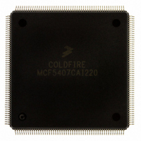
MCF5407CAI220 Freescale Semiconductor, MCF5407CAI220 Datasheet - Page 31

MCF5407CAI220
Manufacturer Part Number
MCF5407CAI220
Description
IC MPU 32B 220MHZ COLDF 208-FQFP
Manufacturer
Freescale Semiconductor
Series
MCF540xr
Specifications of MCF5407CAI220
Core Processor
Coldfire V4
Core Size
32-Bit
Speed
220MHz
Connectivity
EBI/EMI, I²C, UART/USART
Peripherals
DMA, WDT
Number Of I /o
16
Program Memory Type
ROMless
Ram Size
4K x 8
Voltage - Supply (vcc/vdd)
1.65 V ~ 3.6 V
Oscillator Type
External
Operating Temperature
-40°C ~ 85°C
Package / Case
208-FQFP
Processor Series
MCF540x
Core
ColdFire V4
Data Bus Width
32 bit
Program Memory Size
8 KB
Data Ram Size
4 KB
Maximum Clock Frequency
162 MHz
Number Of Programmable I/os
16
Operating Supply Voltage
1.8 V to 3.3 V
Mounting Style
SMD/SMT
3rd Party Development Tools
JLINK-CF-BDM26, EWCF
Cpu Speed
220MHz
Embedded Interface Type
I2C, UART
Digital Ic Case Style
FQFP
No. Of Pins
208
Supply Voltage Range
3.3V
Rohs Compliant
Yes
For Use With
M5407C3 - KIT EVAL FOR MCF5407 W/ETHERNET
Lead Free Status / RoHS Status
Lead free / RoHS Compliant
Eeprom Size
-
Program Memory Size
-
Data Converters
-
Lead Free Status / Rohs Status
Lead free / RoHS Compliant
Available stocks
Company
Part Number
Manufacturer
Quantity
Price
Company:
Part Number:
MCF5407CAI220
Manufacturer:
Freescale
Quantity:
789
Company:
Part Number:
MCF5407CAI220
Manufacturer:
Freescale Semiconductor
Quantity:
10 000
- Current page: 31 of 546
- Download datasheet (7Mb)
Table
Number
8-5
9-1
9-2
9-3
9-4
9-5
9-6
9-7
9-8
10-1
10-2
10-3
10-4
10-5
10-6
10-7
10-8
10-9
10-10
11-1
11-2
11-3
11-4
11-5
11-6
11-7
11-8
11-9
11-10
11-11
11-12
11-13
11-14
11-15
11-16
11-17
11-18
11-19
11-20
11-21
11-22
11-23
11-24
I2SR Field Descriptions................................................................................................ 8-9
Interrupt Controller Registers ....................................................................................... 9-2
Interrupt Control Registers ........................................................................................... 9-2
ICRn Field Descriptions ............................................................................................... 9-3
Interrupt Priority Scheme.............................................................................................. 9-4
AVR Field Descriptions................................................................................................ 9-6
Autovector Register Bit Assignments........................................................................... 9-6
IPR and IMR Field Descriptions................................................................................... 9-7
IRQPAR Field Descriptions ......................................................................................... 9-8
Chip-Select Module Signals ....................................................................................... 10-1
Byte Enables/Byte Write Enable Signal Settings ....................................................... 10-2
Accesses by Matches in CSCRs and DACRs ............................................................. 10-3
D7/AA, Automatic Acknowledge of Boot CS0.......................................................... 10-4
D[6:5]/PS[1:0], Port Size of Boot CS0 ....................................................................... 10-5
D3/BE_CONFIG0, BE[3:0] Boot Configuration ....................................................... 10-5
Chip-Select Registers.................................................................................................. 10-5
CSARn Field Description ........................................................................................... 10-7
CSMRn Field Descriptions ......................................................................................... 10-7
CSCRn Field Descriptions.......................................................................................... 10-8
DRAM Controller Registers ....................................................................................... 11-3
SDRAM Signal Summary .......................................................................................... 11-4
DCR Field Descriptions (Asynchronous Mode)......................................................... 11-5
DACR0/DACR1 Field Description ............................................................................ 11-6
DMR0/DMR1 Field Descriptions............................................................................... 11-7
Generic Address Multiplexing Scheme ...................................................................... 11-8
DRAM Addressing for Byte-Wide Memories.......................................................... 11-10
DRAM Addressing for 16-Bit Wide Memories........................................................ 11-10
DRAM Addressing for 32-Bit Wide Memories........................................................ 11-11
SDRAM Commands ................................................................................................. 11-17
Synchronous DRAM Signal Connections ................................................................ 11-17
DCR Field Descriptions (Synchronous Mode) ......................................................... 11-19
DACR0/DACR1 Field Descriptions (Synchronous Mode)...................................... 11-21
DMR0/DMR1 Field Descriptions............................................................................. 11-23
MCF5407 to SDRAM Interface (8-Bit Port, 9-Column Address Lines).................. 11-24
MCF5407 to SDRAM Interface (8-Bit Port,10-Column Address Lines)................. 11-24
MCF5407 to SDRAM Interface (8-Bit Port,11-Column Address Lines)................. 11-24
MCF5407 to SDRAM Interface (8-Bit Port,12-Column Address Lines)................. 11-24
MCF5407 to SDRAM Interface (8-Bit Port,13-Column Address Lines)................. 11-25
MCF5407 to SDRAM Interface (16-Bit Port, 8-Column Address Lines)................ 11-25
MCF5407 to SDRAM Interface (16-Bit Port, 9-Column Address Lines)................ 11-25
MCF5407 to SDRAM Interface (16-Bit Port, 10-Column Address Lines).............. 11-25
MCF5407 to SDRAM Interface (16-Bit Port, 11-Column Address Lines).............. 11-25
MCF5407 to SDRAM Interface (16-Bit Port, 12-Column Address Lines).............. 11-26
TABLES
Tables
Title
Number
Page
xxxi
Related parts for MCF5407CAI220
Image
Part Number
Description
Manufacturer
Datasheet
Request
R
Part Number:
Description:
Mcf5407 Coldfire Integrated Microprocessor User
Manufacturer:
Freescale Semiconductor, Inc
Datasheet:
Part Number:
Description:
Manufacturer:
Freescale Semiconductor, Inc
Datasheet:
Part Number:
Description:
Manufacturer:
Freescale Semiconductor, Inc
Datasheet:
Part Number:
Description:
Manufacturer:
Freescale Semiconductor, Inc
Datasheet:
Part Number:
Description:
Manufacturer:
Freescale Semiconductor, Inc
Datasheet:
Part Number:
Description:
Manufacturer:
Freescale Semiconductor, Inc
Datasheet:
Part Number:
Description:
Manufacturer:
Freescale Semiconductor, Inc
Datasheet:
Part Number:
Description:
Manufacturer:
Freescale Semiconductor, Inc
Datasheet:
Part Number:
Description:
Manufacturer:
Freescale Semiconductor, Inc
Datasheet:
Part Number:
Description:
Manufacturer:
Freescale Semiconductor, Inc
Datasheet:
Part Number:
Description:
Manufacturer:
Freescale Semiconductor, Inc
Datasheet:
Part Number:
Description:
Manufacturer:
Freescale Semiconductor, Inc
Datasheet:
Part Number:
Description:
Manufacturer:
Freescale Semiconductor, Inc
Datasheet:
Part Number:
Description:
Manufacturer:
Freescale Semiconductor, Inc
Datasheet:
Part Number:
Description:
Manufacturer:
Freescale Semiconductor, Inc
Datasheet:


