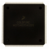
MCF5407CAI220 Freescale Semiconductor, MCF5407CAI220 Datasheet - Page 19

MCF5407CAI220
Manufacturer Part Number
MCF5407CAI220
Description
IC MPU 32B 220MHZ COLDF 208-FQFP
Manufacturer
Freescale Semiconductor
Series
MCF540xr
Specifications of MCF5407CAI220
Core Processor
Coldfire V4
Core Size
32-Bit
Speed
220MHz
Connectivity
EBI/EMI, I²C, UART/USART
Peripherals
DMA, WDT
Number Of I /o
16
Program Memory Type
ROMless
Ram Size
4K x 8
Voltage - Supply (vcc/vdd)
1.65 V ~ 3.6 V
Oscillator Type
External
Operating Temperature
-40°C ~ 85°C
Package / Case
208-FQFP
Processor Series
MCF540x
Core
ColdFire V4
Data Bus Width
32 bit
Program Memory Size
8 KB
Data Ram Size
4 KB
Maximum Clock Frequency
162 MHz
Number Of Programmable I/os
16
Operating Supply Voltage
1.8 V to 3.3 V
Mounting Style
SMD/SMT
3rd Party Development Tools
JLINK-CF-BDM26, EWCF
Cpu Speed
220MHz
Embedded Interface Type
I2C, UART
Digital Ic Case Style
FQFP
No. Of Pins
208
Supply Voltage Range
3.3V
Rohs Compliant
Yes
For Use With
M5407C3 - KIT EVAL FOR MCF5407 W/ETHERNET
Lead Free Status / RoHS Status
Lead free / RoHS Compliant
Eeprom Size
-
Program Memory Size
-
Data Converters
-
Lead Free Status / Rohs Status
Lead free / RoHS Compliant
Available stocks
Company
Part Number
Manufacturer
Quantity
Price
Company:
Part Number:
MCF5407CAI220
Manufacturer:
Freescale
Quantity:
789
Company:
Part Number:
MCF5407CAI220
Manufacturer:
Freescale Semiconductor
Quantity:
10 000
- Current page: 19 of 546
- Download datasheet (7Mb)
20.9
20.10
20.11
A.1
A.2
A.3
A.4
A.5
A.6
A.6.1
A.6.2
A.7
A.8
A.8.1
A.8.2
A.8.2.1
A.8.3
A.8.3.1
A.8.3.2
A.8.3.3
A.8.3.4
A.8.3.5
A.8.4
A.8.5
A.8.6
A.9
A.10
A.11
Paragraph
Number
Migrating from the ColdFire MCF5307 to the MCF5407
Parallel Port (General-Purpose I/O) Timing Specifications ........................... 20-22
DMA Timing Specifications........................................................................... 20-23
IEEE 1149.1 (JTAG) AC Timing Specifications ........................................... 20-24
Overview............................................................................................................ A-1
Instruction Set Additions ................................................................................... A-2
Enhanced Memories........................................................................................... A-3
On-Chip DMA Modifications............................................................................ A-4
UART Enhancements ........................................................................................ A-5
Timing Differences ............................................................................................ A-6
Reset Initialization Modifications...................................................................... A-8
Revision C Debug ............................................................................................ A-10
Voltage Input Changes..................................................................................... A-17
PLL Power Supply Filter Circuit ..................................................................... A-18
Pin-Assignment Compatibility......................................................................... A-18
Phase-Locked Loop (PLL)............................................................................. A-6
Timing Relationships..................................................................................... A-7
Debug Interrupts and Interrupt Requests
On-Chip Breakpoint Registers..................................................................... A-12
Debug Programming Model ........................................................................ A-14
Debug Interrupt Exception Vectors ............................................................. A-15
Processor Status and Debug Data Output Signals ....................................... A-16
Debug C Summary....................................................................................... A-17
in Emulator Mode .................................................................................... A-10
Write Debug Module Register (wdmreg) ................................................ A-12
Address Breakpoint 1 Registers (ABLR1, ABHR1) ............................... A-14
Address Attribute Breakpoint Register 1 (AATR1) ................................ A-14
Program Counter Breakpoint Registers 1–3 (PBR1–PBR3) ................... A-14
Data Breakpoint Register 1 (DBR1, DBMR1) ........................................ A-15
Extended Trigger Definition Register (XTDR) ....................................... A-15
List of Memory Maps
CONTENTS
Appendix A
Appendix B
Contents
Title
Number
Page
xix
Related parts for MCF5407CAI220
Image
Part Number
Description
Manufacturer
Datasheet
Request
R
Part Number:
Description:
Mcf5407 Coldfire Integrated Microprocessor User
Manufacturer:
Freescale Semiconductor, Inc
Datasheet:
Part Number:
Description:
Manufacturer:
Freescale Semiconductor, Inc
Datasheet:
Part Number:
Description:
Manufacturer:
Freescale Semiconductor, Inc
Datasheet:
Part Number:
Description:
Manufacturer:
Freescale Semiconductor, Inc
Datasheet:
Part Number:
Description:
Manufacturer:
Freescale Semiconductor, Inc
Datasheet:
Part Number:
Description:
Manufacturer:
Freescale Semiconductor, Inc
Datasheet:
Part Number:
Description:
Manufacturer:
Freescale Semiconductor, Inc
Datasheet:
Part Number:
Description:
Manufacturer:
Freescale Semiconductor, Inc
Datasheet:
Part Number:
Description:
Manufacturer:
Freescale Semiconductor, Inc
Datasheet:
Part Number:
Description:
Manufacturer:
Freescale Semiconductor, Inc
Datasheet:
Part Number:
Description:
Manufacturer:
Freescale Semiconductor, Inc
Datasheet:
Part Number:
Description:
Manufacturer:
Freescale Semiconductor, Inc
Datasheet:
Part Number:
Description:
Manufacturer:
Freescale Semiconductor, Inc
Datasheet:
Part Number:
Description:
Manufacturer:
Freescale Semiconductor, Inc
Datasheet:
Part Number:
Description:
Manufacturer:
Freescale Semiconductor, Inc
Datasheet:


