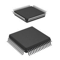
HD64F3644H Renesas Electronics America, HD64F3644H Datasheet - Page 187

HD64F3644H
Manufacturer Part Number
HD64F3644H
Description
IC H8 MCU FLASH 32K 64-QFP
Manufacturer
Renesas Electronics America
Series
H8® H8/300Lr
Datasheet
1.HD64F3644HV.pdf
(551 pages)
Specifications of HD64F3644H
Core Processor
H8/300L
Core Size
8-Bit
Speed
8MHz
Connectivity
SCI
Peripherals
PWM, WDT
Number Of I /o
53
Program Memory Size
32KB (32K x 8)
Program Memory Type
FLASH
Ram Size
1K x 8
Voltage - Supply (vcc/vdd)
2.7 V ~ 5.5 V
Data Converters
A/D 8x8b
Oscillator Type
Internal
Operating Temperature
-20°C ~ 75°C
Package / Case
64-QFP
Package
64PQFP
Family Name
H8
Maximum Speed
8 MHz
Operating Supply Voltage
3.3|5 V
Data Bus Width
8 Bit
Number Of Programmable I/os
45
Interface Type
SCI
On-chip Adc
8-chx8-bit
Number Of Timers
4
Lead Free Status / RoHS Status
Contains lead / RoHS non-compliant
Eeprom Size
-
Available stocks
Company
Part Number
Manufacturer
Quantity
Price
Company:
Part Number:
HD64F3644H
Manufacturer:
HITACHI
Quantity:
490
Company:
Part Number:
HD64F3644H
Manufacturer:
Renesas Electronics America
Quantity:
10 000
Part Number:
HD64F3644H
Manufacturer:
HD
Quantity:
20 000
Company:
Part Number:
HD64F3644HV
Manufacturer:
Renesas
Quantity:
600
Company:
Part Number:
HD64F3644HV
Manufacturer:
Renesas Electronics America
Quantity:
10 000
Part Number:
HD64F3644HV
Manufacturer:
RENESAS/瑞萨
Quantity:
20 000
Part Number:
HD64F3644HV/H83644
Manufacturer:
RENESAS/瑞萨
Quantity:
20 000
- Current page: 187 of 551
- Download datasheet (4Mb)
Table 6.18 Flash Memory AC Characteristics
V
V
T
Item
Programming time *
Erase time *
Reprogramming capability
Verify setup time 1 *
Verify setup time 2 *
Flash memory read setup time *
Notes: 1. Follow the program/erase algorithms shown in section 6 when making the settings.
a
CC
PP
= –20°C to +75°C (regular specifications), T
= 12.0 V ±0.6 V
= 3.0 V to 5.5 V, AV
2. Indicates the programming time per byte (the time during which the P bit is set in the
3. Indicates the time to erase all blocks (32 kB) (the time during which the E bit is set in
4. After powering on when using an external clock, when the programming voltage (V
flash memory control register (FLMCR)). Does not include the program-verify time.
FLMCR). Does not include the prewrite time before erasing of the erase-verify time.
switched from 12 V to V
allowed to elapse before reading the flash memory.
When V
voltage reaches the V
1
*
3
1
PP
1
1
*
2
is released, this specifies the setup time from the point at which the V
CC
= 3.0 V to 5.5 V, AV
4
CC
CC
Symbol
t
t
N
t
t
t
+ 2 V level until the flash memory is read.
P
E
VS1
VS2
FRS
, an interval at least equal to the read setup time must be
WEC
Min
4
2
50
100
a
= –40°C to +85°C (wide-range specifications)
REF
= 3.0 V to AV
Typ
50
1
Rev. 6.00 Sep 12, 2006 page 165 of 526
Max
1000
30
100
CC
, V
SS
Unit
µs
s
Times
µs
µs
µs
= AV
REJ09B0326-0600
SS
Test Conditions
V
V
Section 6 ROM
= 0 V,
CC
CC
≥ 4.5 V
< 4.5 V
PP
PP
) is
Related parts for HD64F3644H
Image
Part Number
Description
Manufacturer
Datasheet
Request
R

Part Number:
Description:
(HD64 Series) Hitachi Single-Chip Microcomputer
Manufacturer:
Hitachi Semiconductor
Datasheet:

Part Number:
Description:
KIT STARTER FOR M16C/29
Manufacturer:
Renesas Electronics America
Datasheet:

Part Number:
Description:
KIT STARTER FOR R8C/2D
Manufacturer:
Renesas Electronics America
Datasheet:

Part Number:
Description:
R0K33062P STARTER KIT
Manufacturer:
Renesas Electronics America
Datasheet:

Part Number:
Description:
KIT STARTER FOR R8C/23 E8A
Manufacturer:
Renesas Electronics America
Datasheet:

Part Number:
Description:
KIT STARTER FOR R8C/25
Manufacturer:
Renesas Electronics America
Datasheet:

Part Number:
Description:
KIT STARTER H8S2456 SHARPE DSPLY
Manufacturer:
Renesas Electronics America
Datasheet:

Part Number:
Description:
KIT STARTER FOR R8C38C
Manufacturer:
Renesas Electronics America
Datasheet:

Part Number:
Description:
KIT STARTER FOR R8C35C
Manufacturer:
Renesas Electronics America
Datasheet:

Part Number:
Description:
KIT STARTER FOR R8CL3AC+LCD APPS
Manufacturer:
Renesas Electronics America
Datasheet:

Part Number:
Description:
KIT STARTER FOR RX610
Manufacturer:
Renesas Electronics America
Datasheet:

Part Number:
Description:
KIT STARTER FOR R32C/118
Manufacturer:
Renesas Electronics America
Datasheet:

Part Number:
Description:
KIT DEV RSK-R8C/26-29
Manufacturer:
Renesas Electronics America
Datasheet:

Part Number:
Description:
KIT STARTER FOR SH7124
Manufacturer:
Renesas Electronics America
Datasheet:

Part Number:
Description:
KIT STARTER FOR H8SX/1622
Manufacturer:
Renesas Electronics America
Datasheet:


