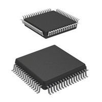
HD64F3644H Renesas Electronics America, HD64F3644H Datasheet - Page 365

HD64F3644H
Manufacturer Part Number
HD64F3644H
Description
IC H8 MCU FLASH 32K 64-QFP
Manufacturer
Renesas Electronics America
Series
H8® H8/300Lr
Datasheet
1.HD64F3644HV.pdf
(551 pages)
Specifications of HD64F3644H
Core Processor
H8/300L
Core Size
8-Bit
Speed
8MHz
Connectivity
SCI
Peripherals
PWM, WDT
Number Of I /o
53
Program Memory Size
32KB (32K x 8)
Program Memory Type
FLASH
Ram Size
1K x 8
Voltage - Supply (vcc/vdd)
2.7 V ~ 5.5 V
Data Converters
A/D 8x8b
Oscillator Type
Internal
Operating Temperature
-20°C ~ 75°C
Package / Case
64-QFP
Package
64PQFP
Family Name
H8
Maximum Speed
8 MHz
Operating Supply Voltage
3.3|5 V
Data Bus Width
8 Bit
Number Of Programmable I/os
45
Interface Type
SCI
On-chip Adc
8-chx8-bit
Number Of Timers
4
Lead Free Status / RoHS Status
Contains lead / RoHS non-compliant
Eeprom Size
-
Available stocks
Company
Part Number
Manufacturer
Quantity
Price
Company:
Part Number:
HD64F3644H
Manufacturer:
HITACHI
Quantity:
490
Company:
Part Number:
HD64F3644H
Manufacturer:
Renesas Electronics America
Quantity:
10 000
Part Number:
HD64F3644H
Manufacturer:
HD
Quantity:
20 000
Company:
Part Number:
HD64F3644HV
Manufacturer:
Renesas
Quantity:
600
Company:
Part Number:
HD64F3644HV
Manufacturer:
Renesas Electronics America
Quantity:
10 000
Part Number:
HD64F3644HV
Manufacturer:
RENESAS/瑞萨
Quantity:
20 000
Part Number:
HD64F3644HV/H83644
Manufacturer:
RENESAS/瑞萨
Quantity:
20 000
- Current page: 365 of 551
- Download datasheet (4Mb)
Bit 0 Clock Select 0 (PWCR0): Bit 0 selects the clock supplied to the 14-bit PWM. This bit is a
write-only bit; it is always read as 1.
Bit 0: PWCR0
0
1
Note:
11.2.2
PWDRU
PWDRL
PWDRU and PWDRL form a 14-bit write-only register, with the upper 6 bits assigned to PWDRU
and the lower 8 bits to PWDRL. The value written to PWDRU and PWDRL gives the total high-
level width of one PWM waveform cycle.
When 14-bit data is written to PWDRU and PWDRL, the register contents are latched in the PWM
waveform generator, updating the PWM waveform generation data. The 14-bit data should always
be written in the following sequence:
1. Write the lower 8 bits to PWDRL.
2.
PWDRU and PWDRL are write-only registers. If they are read, all bits are read as 1.
Bit
Initial value
Read/Write
Bit
Initial value
Read/Write
Write the upper 6 bits to PWDRU.
* t Period of PWM input clock
PWM Data Registers U and L (PWDRU, PWDRL)
PWDRL7 PWDRL6 PWDRL5 PWDRL4 PWDRL3 PWDRL2 PWDRL1 PWDRL0
The input clock is /2 (t * = 2/ ). The conversion period is 16,384/ , with
a minimum modulation width of 1/
The input clock is /4 (t * = 4/ ). The conversion period is 32,768/ , with
a minimum modulation width of 2/ .
Description
W
7
1
7
0
W
1
0
6
6
PWDRU5 PWDRU4 PWDRU3 PWDRU2 PWDRU1 PWDRU0
W
W
0
0
5
5
W
W
4
0
4
0
Rev. 6.00 Sep 12, 2006 page 343 of 526
W
W
3
0
3
0
W
W
2
0
2
0
Section 11 14-Bit PWM
REJ09B0326-0600
W
W
1
0
1
0
(initial value)
W
W
0
0
0
0
Related parts for HD64F3644H
Image
Part Number
Description
Manufacturer
Datasheet
Request
R

Part Number:
Description:
(HD64 Series) Hitachi Single-Chip Microcomputer
Manufacturer:
Hitachi Semiconductor
Datasheet:

Part Number:
Description:
KIT STARTER FOR M16C/29
Manufacturer:
Renesas Electronics America
Datasheet:

Part Number:
Description:
KIT STARTER FOR R8C/2D
Manufacturer:
Renesas Electronics America
Datasheet:

Part Number:
Description:
R0K33062P STARTER KIT
Manufacturer:
Renesas Electronics America
Datasheet:

Part Number:
Description:
KIT STARTER FOR R8C/23 E8A
Manufacturer:
Renesas Electronics America
Datasheet:

Part Number:
Description:
KIT STARTER FOR R8C/25
Manufacturer:
Renesas Electronics America
Datasheet:

Part Number:
Description:
KIT STARTER H8S2456 SHARPE DSPLY
Manufacturer:
Renesas Electronics America
Datasheet:

Part Number:
Description:
KIT STARTER FOR R8C38C
Manufacturer:
Renesas Electronics America
Datasheet:

Part Number:
Description:
KIT STARTER FOR R8C35C
Manufacturer:
Renesas Electronics America
Datasheet:

Part Number:
Description:
KIT STARTER FOR R8CL3AC+LCD APPS
Manufacturer:
Renesas Electronics America
Datasheet:

Part Number:
Description:
KIT STARTER FOR RX610
Manufacturer:
Renesas Electronics America
Datasheet:

Part Number:
Description:
KIT STARTER FOR R32C/118
Manufacturer:
Renesas Electronics America
Datasheet:

Part Number:
Description:
KIT DEV RSK-R8C/26-29
Manufacturer:
Renesas Electronics America
Datasheet:

Part Number:
Description:
KIT STARTER FOR SH7124
Manufacturer:
Renesas Electronics America
Datasheet:

Part Number:
Description:
KIT STARTER FOR H8SX/1622
Manufacturer:
Renesas Electronics America
Datasheet:


