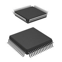
HD64F3644H Renesas Electronics America, HD64F3644H Datasheet - Page 32

HD64F3644H
Manufacturer Part Number
HD64F3644H
Description
IC H8 MCU FLASH 32K 64-QFP
Manufacturer
Renesas Electronics America
Series
H8® H8/300Lr
Datasheet
1.HD64F3644HV.pdf
(551 pages)
Specifications of HD64F3644H
Core Processor
H8/300L
Core Size
8-Bit
Speed
8MHz
Connectivity
SCI
Peripherals
PWM, WDT
Number Of I /o
53
Program Memory Size
32KB (32K x 8)
Program Memory Type
FLASH
Ram Size
1K x 8
Voltage - Supply (vcc/vdd)
2.7 V ~ 5.5 V
Data Converters
A/D 8x8b
Oscillator Type
Internal
Operating Temperature
-20°C ~ 75°C
Package / Case
64-QFP
Package
64PQFP
Family Name
H8
Maximum Speed
8 MHz
Operating Supply Voltage
3.3|5 V
Data Bus Width
8 Bit
Number Of Programmable I/os
45
Interface Type
SCI
On-chip Adc
8-chx8-bit
Number Of Timers
4
Lead Free Status / RoHS Status
Contains lead / RoHS non-compliant
Eeprom Size
-
Available stocks
Company
Part Number
Manufacturer
Quantity
Price
Company:
Part Number:
HD64F3644H
Manufacturer:
HITACHI
Quantity:
490
Company:
Part Number:
HD64F3644H
Manufacturer:
Renesas Electronics America
Quantity:
10 000
Part Number:
HD64F3644H
Manufacturer:
HD
Quantity:
20 000
Company:
Part Number:
HD64F3644HV
Manufacturer:
Renesas
Quantity:
600
Company:
Part Number:
HD64F3644HV
Manufacturer:
Renesas Electronics America
Quantity:
10 000
Part Number:
HD64F3644HV
Manufacturer:
RENESAS/瑞萨
Quantity:
20 000
Part Number:
HD64F3644HV/H83644
Manufacturer:
RENESAS/瑞萨
Quantity:
20 000
- Current page: 32 of 551
- Download datasheet (4Mb)
Section 1 Overview
1.3.2
Table 1.2 outlines the pin functions of the H8/3644 Group.
Table 1.2
Type
Power
source pins
Clock pins
System
control
Rev. 6.00 Sep 12, 2006 page 10 of 526
REJ09B0326-0600
Pin Functions
Symbol
V
V
AV
AV
OSC
OSC
X
X
RES
TEST
Pin Functions
CC
SS
1
2
CC
SS
1
2
FP-64A
33
7
58
3
8
9
6
5
10
4
DP-64S
41
15
2
11
16
17
14
13
18
12
Pin No.
TFP-80C I/O
42
8, 11
72
4
9
10
7
6
12
5
Input
Input
Input
Input
Input
Output
Input
Output
Input
Input
Name and Functions
Power supply: All V
should be connected to the user
system V
Ground: All V
connected to the user system
GND.
Analog power supply: This is
the power supply pin for the A/D
converter. When the A/D
converter is not used, connect
this pin to the user system V
Analog ground: This is the A/D
converter ground pin. It should be
connected to the user system
GND.
System clock: These pins
connect to a crystal or ceramic
resonator, or can be used to input
an external clock.
See section 4, Clock Pulse
Generators, for a typical
connection diagram.
Subclock: These pins connect to
a 32.768-kHz crystal resonator.
See section 4, Clock Pulse
Generators, for a typical
connection diagram.
Reset: When this pin is driven
low, the chip is reset
Test: This is a test pin, not for
use in application systems. It
should be connected to V
CC
.
SS
pins should be
CC
pins
SS
.
CC
.
Related parts for HD64F3644H
Image
Part Number
Description
Manufacturer
Datasheet
Request
R

Part Number:
Description:
(HD64 Series) Hitachi Single-Chip Microcomputer
Manufacturer:
Hitachi Semiconductor
Datasheet:

Part Number:
Description:
KIT STARTER FOR M16C/29
Manufacturer:
Renesas Electronics America
Datasheet:

Part Number:
Description:
KIT STARTER FOR R8C/2D
Manufacturer:
Renesas Electronics America
Datasheet:

Part Number:
Description:
R0K33062P STARTER KIT
Manufacturer:
Renesas Electronics America
Datasheet:

Part Number:
Description:
KIT STARTER FOR R8C/23 E8A
Manufacturer:
Renesas Electronics America
Datasheet:

Part Number:
Description:
KIT STARTER FOR R8C/25
Manufacturer:
Renesas Electronics America
Datasheet:

Part Number:
Description:
KIT STARTER H8S2456 SHARPE DSPLY
Manufacturer:
Renesas Electronics America
Datasheet:

Part Number:
Description:
KIT STARTER FOR R8C38C
Manufacturer:
Renesas Electronics America
Datasheet:

Part Number:
Description:
KIT STARTER FOR R8C35C
Manufacturer:
Renesas Electronics America
Datasheet:

Part Number:
Description:
KIT STARTER FOR R8CL3AC+LCD APPS
Manufacturer:
Renesas Electronics America
Datasheet:

Part Number:
Description:
KIT STARTER FOR RX610
Manufacturer:
Renesas Electronics America
Datasheet:

Part Number:
Description:
KIT STARTER FOR R32C/118
Manufacturer:
Renesas Electronics America
Datasheet:

Part Number:
Description:
KIT DEV RSK-R8C/26-29
Manufacturer:
Renesas Electronics America
Datasheet:

Part Number:
Description:
KIT STARTER FOR SH7124
Manufacturer:
Renesas Electronics America
Datasheet:

Part Number:
Description:
KIT STARTER FOR H8SX/1622
Manufacturer:
Renesas Electronics America
Datasheet:


