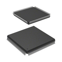
R5S72030W200FP Renesas Electronics America, R5S72030W200FP Datasheet - Page 491

R5S72030W200FP
Manufacturer Part Number
R5S72030W200FP
Description
IC SUPERH MPU ROMLESS 240QFP
Manufacturer
Renesas Electronics America
Series
SuperH® SH7200r
Specifications of R5S72030W200FP
Core Processor
SH2A-FPU
Core Size
32-Bit
Speed
200MHz
Connectivity
CAN, I²C, SCI, SSI, SSU, USB
Peripherals
DMA, LCD, POR, PWM, WDT
Number Of I /o
82
Program Memory Type
ROMless
Ram Size
80K x 8
Voltage - Supply (vcc/vdd)
1.1 V ~ 3.6 V
Data Converters
A/D 8x10b; D/A 2x8b
Oscillator Type
Internal
Operating Temperature
-20°C ~ 85°C
Package / Case
240-QFP
For Use With
R0K572030S000BE - KIT DEV FOR SH7203HS0005KCU11H - EMULATOR E10A-USB H8S(X),SH2(A)
Lead Free Status / RoHS Status
Contains lead / RoHS non-compliant
Eeprom Size
-
Program Memory Size
-
Available stocks
Company
Part Number
Manufacturer
Quantity
Price
Company:
Part Number:
R5S72030W200FP
Manufacturer:
SAMSUNG
Quantity:
1 001
Company:
Part Number:
R5S72030W200FP
Manufacturer:
Renesas Electronics America
Quantity:
10 000
- Current page: 491 of 503
- Download datasheet (3Mb)
8.10
A simple method of calculating required number of clock cycles is described below. This method
provides a rough approximation, but it allows the user to calculate the number of clock cycles
needed to execute the target instruction string.
The calculation is based on the following rules.
(1) The instructions are assumed to already have been fetched, so fetch time is not taken into
consideration.
(2) The 32-bit instructions operate in “execution state” cycles.
(3) If resource contention occurs, the previously issued instructions operate in “execution state”
cycles. Parallel execution of subsequent instructions is not possible.
(4) If the result from the previously issued instruction is used by the instruction that immediately
follows, the calculation assumes that the previously issued instruction will require “latency”
cycles.
(5) If the result from the previously issued instruction is not used by the instruction that
immediately follows, the calculation assumes that the previously issued instruction will require
“execution state” cycles.
(6) Correction for parallel execution is performed in simplified form as a compensation item.
There are a large number of exceptional cases, so the calculation method introduced here cannot
be 100% accurate. It does allow the user to obtain a rough idea of the number of clock cycles that
will be required, however. Examples are provided below.
1. Counting Latency Cycles
The result from MOV.L, which precedes ADD, will be used, so the calculation assumes that
MOV.L will require “latency” cycles (two cycles) to execute. The next MOV.L instruction uses
the result from ADD, so the calculation assumes that the ADD instruction will require “latency”
execution (one cycle).
MOV.L
ADD
MOV.L
Simple Method of Calculating Required Number of Clock Cycles
@ R1, R0
R0, @ R1
# imm, R0
↔
↔
—
ID
↔
EX
—
—
↔
MA
ID
Rev. 3.00 Jul 08, 2005 page 475 of 484
↔
WB
EX
ID
↔
EX
Section 8 Pipeline Operation
↔
MA
REJ09B0051-0300
↔
Cycles
2
1
Related parts for R5S72030W200FP
Image
Part Number
Description
Manufacturer
Datasheet
Request
R

Part Number:
Description:
KIT STARTER FOR M16C/29
Manufacturer:
Renesas Electronics America
Datasheet:

Part Number:
Description:
KIT STARTER FOR R8C/2D
Manufacturer:
Renesas Electronics America
Datasheet:

Part Number:
Description:
R0K33062P STARTER KIT
Manufacturer:
Renesas Electronics America
Datasheet:

Part Number:
Description:
KIT STARTER FOR R8C/23 E8A
Manufacturer:
Renesas Electronics America
Datasheet:

Part Number:
Description:
KIT STARTER FOR R8C/25
Manufacturer:
Renesas Electronics America
Datasheet:

Part Number:
Description:
KIT STARTER H8S2456 SHARPE DSPLY
Manufacturer:
Renesas Electronics America
Datasheet:

Part Number:
Description:
KIT STARTER FOR R8C38C
Manufacturer:
Renesas Electronics America
Datasheet:

Part Number:
Description:
KIT STARTER FOR R8C35C
Manufacturer:
Renesas Electronics America
Datasheet:

Part Number:
Description:
KIT STARTER FOR R8CL3AC+LCD APPS
Manufacturer:
Renesas Electronics America
Datasheet:

Part Number:
Description:
KIT STARTER FOR RX610
Manufacturer:
Renesas Electronics America
Datasheet:

Part Number:
Description:
KIT STARTER FOR R32C/118
Manufacturer:
Renesas Electronics America
Datasheet:

Part Number:
Description:
KIT DEV RSK-R8C/26-29
Manufacturer:
Renesas Electronics America
Datasheet:

Part Number:
Description:
KIT STARTER FOR SH7124
Manufacturer:
Renesas Electronics America
Datasheet:

Part Number:
Description:
KIT STARTER FOR H8SX/1622
Manufacturer:
Renesas Electronics America
Datasheet:

Part Number:
Description:
KIT DEV FOR SH7203
Manufacturer:
Renesas Electronics America
Datasheet:


