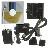
Z8F16800144ZCOG Zilog, Z8F16800144ZCOG Datasheet - Page 123

Z8F16800144ZCOG
Manufacturer Part Number
Z8F16800144ZCOG
Description
KIT DEV FOR Z8F642 MCU 44 PIN
Manufacturer
Zilog
Series
Z8 Encore!®r
Type
MCUr
Specifications of Z8F16800144ZCOG
Contents
Hardware, Software and Documentation
For Use With/related Products
Z8F642
For Use With
269-4661 - KIT ACC ETHERNET SMART CABLE
Lead Free Status / RoHS Status
Lead free / RoHS Compliant
Other names
269-4678
- Current page: 123 of 399
- Download datasheet (19Mb)
Table 56. Timer 0–2 PWM0 High Byte Register (TxPWM0H)
Table 57. Timer 0–2 PWM0 Low Byte Register (TxPWM0L)
Table 58. Timer 0-2 PWM1 High Byte Register (TxPWM1H)
PS025011-1010
BITS
FIELD
RESET
R/W
ADDR
BITS
FIELD
RESET
R/W
ADDR
BITS
FIELD
RESET
R/W
ADDR
Timer 0
R/W
R/W
R/W
7
0
7
0
7
0
PWM0H and PWM0L—Pulse Width Modulator 0 High and Low Bytes
These two bytes, {PWM0H[7:0], PWM0L[7:0]}, form a 16-bit value that is compared to
the current 16-bit timer count. When a match occurs, the PWM output changes state. The
PWM output value is set by the TPOL bit in the Timer Control 1 register (TxCTL1).
The TxPWM0H and TxPWM0L registers also store the 16-bit captured timer value when
operating in CAPTURE, CAPTURE/COMPARE, and DEMODULATION modes.
The Timer 0
(see
–
2 PWM1 High and Low Byte Registers
Table 58
R/W
R/W
R/W
6
0
6
0
6
0
–
2 PWM1 High and Low Byte (TxPWM1H and TxPWM1L) registers
and
Table
R/W
R/W
R/W
5
0
5
0
5
0
59) store Capture values for DEMODULATION mode.
P R E L I M I N A R Y
F04H, F0CH, F14H
F05H, F0DH, F15H
F20H, F24H, F28H
R/W
R/W
R/W
4
0
4
0
4
0
PWM0H
PWM1H
PWM0L
R/W
R/W
R/W
3
0
3
0
3
0
Z8 Encore! XP
R/W
R/W
R/W
2
0
2
0
2
0
Product Specification
R/W
R/W
R/W
1
0
1
0
1
0
®
F1680 Series
R/W
R/W
R/W
0
0
0
0
0
0
Timers
109
Related parts for Z8F16800144ZCOG
Image
Part Number
Description
Manufacturer
Datasheet
Request
R

Part Number:
Description:
Communication Controllers, ZILOG INTELLIGENT PERIPHERAL CONTROLLER (ZIP)
Manufacturer:
Zilog, Inc.
Datasheet:

Part Number:
Description:
KIT DEV FOR Z8 ENCORE 16K TO 64K
Manufacturer:
Zilog
Datasheet:

Part Number:
Description:
KIT DEV Z8 ENCORE XP 28-PIN
Manufacturer:
Zilog
Datasheet:

Part Number:
Description:
DEV KIT FOR Z8 ENCORE 8K/4K
Manufacturer:
Zilog
Datasheet:

Part Number:
Description:
KIT DEV Z8 ENCORE XP 28-PIN
Manufacturer:
Zilog
Datasheet:

Part Number:
Description:
DEV KIT FOR Z8 ENCORE 4K TO 8K
Manufacturer:
Zilog
Datasheet:

Part Number:
Description:
CMOS Z8 microcontroller. ROM 16 Kbytes, RAM 256 bytes, speed 16 MHz, 32 lines I/O, 3.0V to 5.5V
Manufacturer:
Zilog, Inc.
Datasheet:

Part Number:
Description:
Low-cost microcontroller. 512 bytes ROM, 61 bytes RAM, 8 MHz
Manufacturer:
Zilog, Inc.
Datasheet:

Part Number:
Description:
Z8 4K OTP Microcontroller
Manufacturer:
Zilog, Inc.
Datasheet:

Part Number:
Description:
CMOS SUPER8 ROMLESS MCU
Manufacturer:
Zilog, Inc.
Datasheet:

Part Number:
Description:
SL1866 CMOSZ8 OTP Microcontroller
Manufacturer:
Zilog, Inc.
Datasheet:

Part Number:
Description:
SL1866 CMOSZ8 OTP Microcontroller
Manufacturer:
Zilog, Inc.
Datasheet:

Part Number:
Description:
OTP (KB) = 1, RAM = 125, Speed = 12, I/O = 14, 8-bit Timers = 2, Comm Interfaces Other Features = Por, LV Protect, Voltage = 4.5-5.5V
Manufacturer:
Zilog, Inc.
Datasheet:

Part Number:
Description:
Manufacturer:
Zilog, Inc.
Datasheet:


