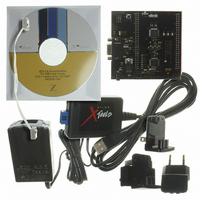
Z8F16800144ZCOG Zilog, Z8F16800144ZCOG Datasheet - Page 165

Z8F16800144ZCOG
Manufacturer Part Number
Z8F16800144ZCOG
Description
KIT DEV FOR Z8F642 MCU 44 PIN
Manufacturer
Zilog
Series
Z8 Encore!®r
Type
MCUr
Specifications of Z8F16800144ZCOG
Contents
Hardware, Software and Documentation
For Use With/related Products
Z8F642
For Use With
269-4661 - KIT ACC ETHERNET SMART CABLE
Lead Free Status / RoHS Status
Lead free / RoHS Compliant
Other names
269-4678
- Current page: 165 of 399
- Download datasheet (19Mb)
PS025011-1010
LIN System Clock Requirements
The LIN Master provides the timing reference for the LIN network and is required to have
a clock source with a tolerance of ±0.5%. A slave with autobaud capability is required to
have a baud clock matching the master oscillator within ±14%. The slave nodes autobaud
to lock onto the master timing reference with an accuracy of ±2%. If a slave does not
contain autobaud capability it must include a baud clock which deviates from the masters
by not more than ±1.5%. These accuracy requirements must include the effects such as
voltage and temperature drift during operation.
Before sending/receiving messages, the Baud Reload High/Low registers must be
initialized. Unlike standard UART modes, the Baud Reload High/Low registers must be
loaded with the baud interval rather than 1/16 of the baud interval.
In order to autobaud with the required accuracy, the LIN Slave system clock must be at
least 100 times the baud rate.
LIN Mode Initialization and Operation
The LIN protocol mode is selected by setting either the
(LIN Slave), and optionally (for LIN slave) the
Control Register. To access the LIN Control Register, the
LIN-UART Mode Select/Status register must be = 010B. The LIN-UART Control0
register must be initialized with
In addition to the
LinState
is initially set by software. In the LIN SLAVE mode, the
hardware as the slave moves through the Wait For Break, AutoBaud, and Active states.
LIN MASTER Mode Operation
LIN MASTER mode is selected by setting
LinState
LIN sleep state, the
The Break is the first part of the message frame transmitted by the master, consisting of at
least 13 bit periods of logical zero on the LIN bus. During initialization of the LIN master,
the duration (in bit times) of the Break is written to the
Control Register. The transmission of the Break is performed by setting the
Control 0 Register. The LIN-UART starts the Break once the
character transmission currently underway has completed. The
hardware till the break is completed.
If it is necessary to generate a Break longer than 15 bit times, the
normal UART mode where software times the duration of the Break.
[1:0] field exists which defines the current state of the LIN logic. This field
[1:0] =
LMST
11B.
LinState
,
LSLV
If the LIN bus protocol indicates the bus is required go into the
P R E L I M I N A R Y
, and
[1:0] bits must be set to
TEN
ABEN
= 1,
bits in the LIN Control Register, a
REN
LMST
= 1, and all other bits = 0.
ABEN
= 1,
(Autobaud Enable) bits in the LIN
LSLV
00B
TxBreakLength
Z8 Encore! XP
LMST
LinState
MSEL
= 0,
by software.
SBRK
(LIN Master) or
SBRK
(Mode Select) field of the
Product Specification
ABEN
SBRK
bit is set and any
field is updated by
bit is deasserted by
= 0, and
bit can be used in
®
field of the LIN
F1680 Series
SBRK
LSLV
LIN-UART
bit in the
151
Related parts for Z8F16800144ZCOG
Image
Part Number
Description
Manufacturer
Datasheet
Request
R

Part Number:
Description:
Communication Controllers, ZILOG INTELLIGENT PERIPHERAL CONTROLLER (ZIP)
Manufacturer:
Zilog, Inc.
Datasheet:

Part Number:
Description:
KIT DEV FOR Z8 ENCORE 16K TO 64K
Manufacturer:
Zilog
Datasheet:

Part Number:
Description:
KIT DEV Z8 ENCORE XP 28-PIN
Manufacturer:
Zilog
Datasheet:

Part Number:
Description:
DEV KIT FOR Z8 ENCORE 8K/4K
Manufacturer:
Zilog
Datasheet:

Part Number:
Description:
KIT DEV Z8 ENCORE XP 28-PIN
Manufacturer:
Zilog
Datasheet:

Part Number:
Description:
DEV KIT FOR Z8 ENCORE 4K TO 8K
Manufacturer:
Zilog
Datasheet:

Part Number:
Description:
CMOS Z8 microcontroller. ROM 16 Kbytes, RAM 256 bytes, speed 16 MHz, 32 lines I/O, 3.0V to 5.5V
Manufacturer:
Zilog, Inc.
Datasheet:

Part Number:
Description:
Low-cost microcontroller. 512 bytes ROM, 61 bytes RAM, 8 MHz
Manufacturer:
Zilog, Inc.
Datasheet:

Part Number:
Description:
Z8 4K OTP Microcontroller
Manufacturer:
Zilog, Inc.
Datasheet:

Part Number:
Description:
CMOS SUPER8 ROMLESS MCU
Manufacturer:
Zilog, Inc.
Datasheet:

Part Number:
Description:
SL1866 CMOSZ8 OTP Microcontroller
Manufacturer:
Zilog, Inc.
Datasheet:

Part Number:
Description:
SL1866 CMOSZ8 OTP Microcontroller
Manufacturer:
Zilog, Inc.
Datasheet:

Part Number:
Description:
OTP (KB) = 1, RAM = 125, Speed = 12, I/O = 14, 8-bit Timers = 2, Comm Interfaces Other Features = Por, LV Protect, Voltage = 4.5-5.5V
Manufacturer:
Zilog, Inc.
Datasheet:

Part Number:
Description:
Manufacturer:
Zilog, Inc.
Datasheet:


