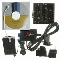
Z8F16800144ZCOG Zilog, Z8F16800144ZCOG Datasheet - Page 219

Z8F16800144ZCOG
Manufacturer Part Number
Z8F16800144ZCOG
Description
KIT DEV FOR Z8F642 MCU 44 PIN
Manufacturer
Zilog
Series
Z8 Encore!®r
Type
MCUr
Specifications of Z8F16800144ZCOG
Contents
Hardware, Software and Documentation
For Use With/related Products
Z8F642
For Use With
269-4661 - KIT ACC ETHERNET SMART CABLE
Lead Free Status / RoHS Status
Lead free / RoHS Compliant
Other names
269-4678
- Current page: 219 of 399
- Download datasheet (19Mb)
ESPI Control Register Definitions
PS025011-1010
ESPI Baud Rate Generator
ESPI Data Register
In ESPI Master mode, the Baud Rate Generator creates a lower frequency serial clock
(SCK) for data transmission synchronization between the Master and the external Slave.
The input to the Baud Rate Generator is the system clock. The ESPI Baud Rate High and
Low Byte registers combine to form a 16-bit reload value, BRG[15:0], for the ESPI Baud
Rate Generator. The ESPI baud rate is calculated using the following equation:
Minimum baud rate is obtained by setting BRG[15:0] to 0000H for a clock divisor value
of (2 x 65536 = 131072).
When the ESPI is disabled, the Baud Rate Generator can function as a basic 16-bit timer
with interrupt on timeout. Follow the steps below to configure the Baud Rate Generator as
a timer with interrupt on timeout:
1. Disable the ESPI by clearing the ESPIEN1,0 bits in the ESPI Control register.
2. Load the desired 16-bit count value into the ESPI Baud Rate High and Low Byte
3. Enable the Baud Rate Generator timer function and associated interrupt by setting the
The ESPI Data register (see
data register and the incoming receive data register. Reads from the ESPI Data register
return the contents of the receive data register. The receive data register is updated with
the contents of the shift register at the end of each transfer. Writes to the ESPI Data regis-
ter load the transmit data register unless TDRE = 0. Data is shifted out starting with bit 7.
The last bit received resides in bit position 0.
With the ESPI configured as a Master, writing a data byte to this register initiates the data
transmission. With the ESPI configured as a Slave, writing a data byte to this register
loads the shift register in preparation for the next data transfer with the external Master. In
either the MASTER or SLAVE modes, if TDRE = 0, writes to this register are ignored.
When the character length is less than 8 bits (as set by the NUMBITS field in the ESPI
Mode register), the transmit character must be left justified in the ESPI Data register. A
received character of less than 8 bits is right justified (last bit received is in bit position 0).
For example, if the ESPI is configured for 4-bit characters, the transmit characters must be
written to ESPIDATA[7:4] and the received characters are read from ESPIDATA[3:0]
I Baud Rate bits s
registers.
BRGCTL bit in the ESPI Control register to 1.
P R E L I M I N A R Y
Table 110
=
System Clock Frequency Hz
-------------------------------------------------------------------------------------- -
on page 206) addresses both the outgoing transmit
2
BRG[15:0]
Z8 Encore! XP
Enhanced Serial Peripheral Interface
Product Specification
®
F1680 Series
205
Related parts for Z8F16800144ZCOG
Image
Part Number
Description
Manufacturer
Datasheet
Request
R

Part Number:
Description:
Communication Controllers, ZILOG INTELLIGENT PERIPHERAL CONTROLLER (ZIP)
Manufacturer:
Zilog, Inc.
Datasheet:

Part Number:
Description:
KIT DEV FOR Z8 ENCORE 16K TO 64K
Manufacturer:
Zilog
Datasheet:

Part Number:
Description:
KIT DEV Z8 ENCORE XP 28-PIN
Manufacturer:
Zilog
Datasheet:

Part Number:
Description:
DEV KIT FOR Z8 ENCORE 8K/4K
Manufacturer:
Zilog
Datasheet:

Part Number:
Description:
KIT DEV Z8 ENCORE XP 28-PIN
Manufacturer:
Zilog
Datasheet:

Part Number:
Description:
DEV KIT FOR Z8 ENCORE 4K TO 8K
Manufacturer:
Zilog
Datasheet:

Part Number:
Description:
CMOS Z8 microcontroller. ROM 16 Kbytes, RAM 256 bytes, speed 16 MHz, 32 lines I/O, 3.0V to 5.5V
Manufacturer:
Zilog, Inc.
Datasheet:

Part Number:
Description:
Low-cost microcontroller. 512 bytes ROM, 61 bytes RAM, 8 MHz
Manufacturer:
Zilog, Inc.
Datasheet:

Part Number:
Description:
Z8 4K OTP Microcontroller
Manufacturer:
Zilog, Inc.
Datasheet:

Part Number:
Description:
CMOS SUPER8 ROMLESS MCU
Manufacturer:
Zilog, Inc.
Datasheet:

Part Number:
Description:
SL1866 CMOSZ8 OTP Microcontroller
Manufacturer:
Zilog, Inc.
Datasheet:

Part Number:
Description:
SL1866 CMOSZ8 OTP Microcontroller
Manufacturer:
Zilog, Inc.
Datasheet:

Part Number:
Description:
OTP (KB) = 1, RAM = 125, Speed = 12, I/O = 14, 8-bit Timers = 2, Comm Interfaces Other Features = Por, LV Protect, Voltage = 4.5-5.5V
Manufacturer:
Zilog, Inc.
Datasheet:

Part Number:
Description:
Manufacturer:
Zilog, Inc.
Datasheet:


