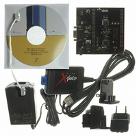
Z8F16800144ZCOG Zilog, Z8F16800144ZCOG Datasheet - Page 161

Z8F16800144ZCOG
Manufacturer Part Number
Z8F16800144ZCOG
Description
KIT DEV FOR Z8F642 MCU 44 PIN
Manufacturer
Zilog
Series
Z8 Encore!®r
Type
MCUr
Specifications of Z8F16800144ZCOG
Contents
Hardware, Software and Documentation
For Use With/related Products
Z8F642
For Use With
269-4661 - KIT ACC ETHERNET SMART CABLE
Lead Free Status / RoHS Status
Lead free / RoHS Compliant
Other names
269-4678
- Current page: 161 of 399
- Download datasheet (19Mb)
PS025011-1010
Clear To Send Operation
External Driver Enable
Figure 22. LIN-UART Driver Enable Signal Timing with One Stop Bit and Parity
The Clear To Send (CTS) pin, if enabled by the
Register performs flow control on the outgoing transmit data stream. The Clear To Send
(CTS) input pin is sampled one system clock before any new character transmission
begins. To delay transmission of the next data character, an external receiver must reduce
CTS at least one system clock cycle before a new data transmission begins. For multiple
character transmissions, this operation is typically performed during the stop bit
transmission. If CTS stops in the middle of a character transmission, the current character
is sent completely.
The LIN-UART provides a Driver Enable (DE) signal for off-chip bus transceivers. This
feature reduces the software overhead associated using a GPIO pin to control the trans-
ceiver when communicating on a multitransceiver bus, such as RS-485.
Driver Enable is a programmable polarity signal which envelopes the entire transmitted
data frame including parity and stop bits as illustrated in
signal asserts when a byte is written to the LIN-UART Transmit Data Register. The Driver
Enable signal asserts at least one bit period and no greater than two bit periods before the
start bit is transmitted. This allows a set-up time to enable the transceiver. The Driver
Enable signal deasserts one system clock period after the last stop bit is transmitted. This
system clock delay allows both time for data to clear the transceiver before disabling it, as
well as the ability to determine if another character follows the current character. In the
event of back-to-back characters (new data must be written to the Transmit Data Register
before the previous character is completely transmitted) the DE signal is not deassertd
between characters. The
LIN-UART Control Register 1 sets the polarity of the Driver Enable signal.
DEPOL
P R E L I M I N A R Y
bit in the
CTSE
bit of the LIN-UART Control 0
Z8 Encore! XP
Figure
22. The Driver Enable
Product Specification
®
F1680 Series
LIN-UART
147
Related parts for Z8F16800144ZCOG
Image
Part Number
Description
Manufacturer
Datasheet
Request
R

Part Number:
Description:
Communication Controllers, ZILOG INTELLIGENT PERIPHERAL CONTROLLER (ZIP)
Manufacturer:
Zilog, Inc.
Datasheet:

Part Number:
Description:
KIT DEV FOR Z8 ENCORE 16K TO 64K
Manufacturer:
Zilog
Datasheet:

Part Number:
Description:
KIT DEV Z8 ENCORE XP 28-PIN
Manufacturer:
Zilog
Datasheet:

Part Number:
Description:
DEV KIT FOR Z8 ENCORE 8K/4K
Manufacturer:
Zilog
Datasheet:

Part Number:
Description:
KIT DEV Z8 ENCORE XP 28-PIN
Manufacturer:
Zilog
Datasheet:

Part Number:
Description:
DEV KIT FOR Z8 ENCORE 4K TO 8K
Manufacturer:
Zilog
Datasheet:

Part Number:
Description:
CMOS Z8 microcontroller. ROM 16 Kbytes, RAM 256 bytes, speed 16 MHz, 32 lines I/O, 3.0V to 5.5V
Manufacturer:
Zilog, Inc.
Datasheet:

Part Number:
Description:
Low-cost microcontroller. 512 bytes ROM, 61 bytes RAM, 8 MHz
Manufacturer:
Zilog, Inc.
Datasheet:

Part Number:
Description:
Z8 4K OTP Microcontroller
Manufacturer:
Zilog, Inc.
Datasheet:

Part Number:
Description:
CMOS SUPER8 ROMLESS MCU
Manufacturer:
Zilog, Inc.
Datasheet:

Part Number:
Description:
SL1866 CMOSZ8 OTP Microcontroller
Manufacturer:
Zilog, Inc.
Datasheet:

Part Number:
Description:
SL1866 CMOSZ8 OTP Microcontroller
Manufacturer:
Zilog, Inc.
Datasheet:

Part Number:
Description:
OTP (KB) = 1, RAM = 125, Speed = 12, I/O = 14, 8-bit Timers = 2, Comm Interfaces Other Features = Por, LV Protect, Voltage = 4.5-5.5V
Manufacturer:
Zilog, Inc.
Datasheet:

Part Number:
Description:
Manufacturer:
Zilog, Inc.
Datasheet:


