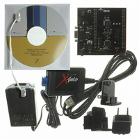
Z8F16800144ZCOG Zilog, Z8F16800144ZCOG Datasheet - Page 248

Z8F16800144ZCOG
Manufacturer Part Number
Z8F16800144ZCOG
Description
KIT DEV FOR Z8F642 MCU 44 PIN
Manufacturer
Zilog
Series
Z8 Encore!®r
Type
MCUr
Specifications of Z8F16800144ZCOG
Contents
Hardware, Software and Documentation
For Use With/related Products
Z8F642
For Use With
269-4661 - KIT ACC ETHERNET SMART CABLE
Lead Free Status / RoHS Status
Lead free / RoHS Compliant
Other names
269-4678
- Current page: 248 of 399
- Download datasheet (19Mb)
PS025011-1010
S
Slave Address
1st Byte
Figure 50. Data Transfer Format—Slave Transmit Transaction with 10-Bit Address
12. The software responds to the
Slave Transmit Transaction With 10-Bit Address
The data transfer format for a master reading data from a slave with 10-bit addressing
is displayed in
Controller operating as a slave in 10-bit addressing mode, transmitting data to the bus
master.
1. The software configures the controller for operation as a slave in 10-bit addressing
2. The Master initiates a transfer by sending the first address byte. The SLAVE mode I
3. The Master sends the second address byte. The SLAVE mode I
4. The software responds to the slave address match interrupt by reading the I2CISTAT
5. The Master sees the Acknowledge and sends a
W = 0 A
Register, which clears the
mode.
(a) Initialize the
(b) Optionally set the
(c) Initialize the
(d) Set
controller recognizes the start of a 10-bit address with a match to
detects R/W bit = 0 (a Write from the master to the slave). The I
acknowledges indicating it is available to accept the transaction.
the second address byte with the value in
the I2CISTAT Register is set = 1, causing a slave address match interrupt. The
is set = 0, indicating a write to the slave. If a match occurs, the I
acknowledges on the I
Register, which clears the
required.
first address byte with R/W set to 1. The SLAVE mode I
RESTART
and detects R/W = 1 (the master reads from the slave). The slave I
the
The
SAM
or MASTER/SLAVE mode with 10-bit addressing.
MODE Register.
RD
IEN
bit is set = 1. The SLAVE mode I
bit in the I2CISTAT Register which causes the slave address match interrupt.
instruction followed by the first address byte with a match to
Slave Address
Figure
= 1, and
2nd Byte
MODE
SLA[7:0]
50. The following procedure describes the I
NAK
GCE
2
field in the I
C bus, indicating it is available to accept the data.
P R E L I M I N A R Y
= 0 in the I
SPRS
SAM
A
bit.
bits in the I2CSLVAD Register and
STOP/RESTART
S
bit. Because the
bit.
Slave Address
2
C Mode Register for either SLAVE ONLY mode
2
1st Byte
C Control Register.
SLA[7:0]
2
C controller acknowledges on the bus.
interrupt by reading the I2CISTAT
RESTART
RD
R = 1 A Data A Data A
bit = 0, no further action is
Z8 Encore! XP
. If there is a match, the
2
instruction, followed by the
C controller recognizes the
Product Specification
I2C Master/Slave Controller
2
2
C Master/Slave
C controller compares
2
SLA[9:8]
2
C controller
C controller
SLA[9:8]
2
C controller sets
®
F1680 Series
SLA[9:8]
in the I2C
SAM
and
RD
bit in
bit
,
2
P
C
234
Related parts for Z8F16800144ZCOG
Image
Part Number
Description
Manufacturer
Datasheet
Request
R

Part Number:
Description:
Communication Controllers, ZILOG INTELLIGENT PERIPHERAL CONTROLLER (ZIP)
Manufacturer:
Zilog, Inc.
Datasheet:

Part Number:
Description:
KIT DEV FOR Z8 ENCORE 16K TO 64K
Manufacturer:
Zilog
Datasheet:

Part Number:
Description:
KIT DEV Z8 ENCORE XP 28-PIN
Manufacturer:
Zilog
Datasheet:

Part Number:
Description:
DEV KIT FOR Z8 ENCORE 8K/4K
Manufacturer:
Zilog
Datasheet:

Part Number:
Description:
KIT DEV Z8 ENCORE XP 28-PIN
Manufacturer:
Zilog
Datasheet:

Part Number:
Description:
DEV KIT FOR Z8 ENCORE 4K TO 8K
Manufacturer:
Zilog
Datasheet:

Part Number:
Description:
CMOS Z8 microcontroller. ROM 16 Kbytes, RAM 256 bytes, speed 16 MHz, 32 lines I/O, 3.0V to 5.5V
Manufacturer:
Zilog, Inc.
Datasheet:

Part Number:
Description:
Low-cost microcontroller. 512 bytes ROM, 61 bytes RAM, 8 MHz
Manufacturer:
Zilog, Inc.
Datasheet:

Part Number:
Description:
Z8 4K OTP Microcontroller
Manufacturer:
Zilog, Inc.
Datasheet:

Part Number:
Description:
CMOS SUPER8 ROMLESS MCU
Manufacturer:
Zilog, Inc.
Datasheet:

Part Number:
Description:
SL1866 CMOSZ8 OTP Microcontroller
Manufacturer:
Zilog, Inc.
Datasheet:

Part Number:
Description:
SL1866 CMOSZ8 OTP Microcontroller
Manufacturer:
Zilog, Inc.
Datasheet:

Part Number:
Description:
OTP (KB) = 1, RAM = 125, Speed = 12, I/O = 14, 8-bit Timers = 2, Comm Interfaces Other Features = Por, LV Protect, Voltage = 4.5-5.5V
Manufacturer:
Zilog, Inc.
Datasheet:

Part Number:
Description:
Manufacturer:
Zilog, Inc.
Datasheet:


