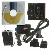
Z8F16800144ZCOG Zilog, Z8F16800144ZCOG Datasheet - Page 55

Z8F16800144ZCOG
Manufacturer Part Number
Z8F16800144ZCOG
Description
KIT DEV FOR Z8F642 MCU 44 PIN
Manufacturer
Zilog
Series
Z8 Encore!®r
Type
MCUr
Specifications of Z8F16800144ZCOG
Contents
Hardware, Software and Documentation
For Use With/related Products
Z8F642
For Use With
269-4661 - KIT ACC ETHERNET SMART CABLE
Lead Free Status / RoHS Status
Lead free / RoHS Compliant
Other names
269-4678
- Current page: 55 of 399
- Download datasheet (19Mb)
Low-Voltage Detection
PS025011-1010
Caution:
Stop Mode Recovery Using Comparator Interrupt
Stop Mode Recovery Using GPIO Port Pin Transition
Stop Mode Recovery Using External RESET Pin
If Comparator enabled for STOP mode operation interrupts during STOP mode, the device
undergoes a Stop Mode Recovery sequence. In the Reset Status Register, the
set to 1. If the Z8 Encore! XP F1680 Series device is configured to respond to interrupts,
the eZ8 CPU services the comparator interrupt request following the normal Stop Mode
Recovery sequence.
Each of the GPIO Port pins may be configured as a Stop Mode Recovery input source.
On any GPIO pin enabled as a Stop Mode Recovery source, a change in the input pin
value (from high to low or from low to high) initiates Stop Mode Recovery. In the Reset
Status register, the
When the Z8 Encore! XP F1680 Series device is in STOP mode and the external RESET
pin is driven Low, a System Reset occurs. Because of a glitch filter operating on the
RESET pin, the low pulse must be greater than the minimum width specified, or it is
ignored. For details, see
In addition to the VBO Reset described earlier, it is also possible to generate an interrupt
when the supply voltage drops below a user-selected value. For more details on the
available Low-Voltage Detection (LVD) threshold levels, see
page 273.
When the supply voltage drops below the LVD threshold, the
Register is set to 1. This bit remains 1 until the low-voltage condition elapses. Reading or
writing this bit does not clear it. The LVD circuit can also generate an interrupt when
enabled
the interrupt is the only way to guarantee detection of a transient low-voltage event.
The LVD circuit is either enabled or disabled by the Power Control Register bit 4. For
more details, see
In STOP mode, the GPIO Port Input Data registers (PxIN) are disabled. The Port Input
Data registers record the Port transition only if the signal stays on the Port pin till the
end of the Stop Mode Recovery delay. As a result, short pulses on the Port pin can
initiate Stop Mode Recovery without being written to the Port Input Data register or
without initiating an interrupt (if enabled for that pin).
(Interrupt Vectors and Priority
Power Control Register Definitions
STOP
Electrical Characteristics
bit is set to 1.
P R E L I M I N A R Y
on page 74). The LVD is not latched, so enabling
Reset, Stop Mode Recovery, and Low-Voltage
on page 339.
on page 47.
Z8 Encore! XP
Trim Bit Address 0000H
LVD
Product Specification
bit of the RSTSTAT
®
F1680 Series
STOP
bit is
on
41
Related parts for Z8F16800144ZCOG
Image
Part Number
Description
Manufacturer
Datasheet
Request
R

Part Number:
Description:
Communication Controllers, ZILOG INTELLIGENT PERIPHERAL CONTROLLER (ZIP)
Manufacturer:
Zilog, Inc.
Datasheet:

Part Number:
Description:
KIT DEV FOR Z8 ENCORE 16K TO 64K
Manufacturer:
Zilog
Datasheet:

Part Number:
Description:
KIT DEV Z8 ENCORE XP 28-PIN
Manufacturer:
Zilog
Datasheet:

Part Number:
Description:
DEV KIT FOR Z8 ENCORE 8K/4K
Manufacturer:
Zilog
Datasheet:

Part Number:
Description:
KIT DEV Z8 ENCORE XP 28-PIN
Manufacturer:
Zilog
Datasheet:

Part Number:
Description:
DEV KIT FOR Z8 ENCORE 4K TO 8K
Manufacturer:
Zilog
Datasheet:

Part Number:
Description:
CMOS Z8 microcontroller. ROM 16 Kbytes, RAM 256 bytes, speed 16 MHz, 32 lines I/O, 3.0V to 5.5V
Manufacturer:
Zilog, Inc.
Datasheet:

Part Number:
Description:
Low-cost microcontroller. 512 bytes ROM, 61 bytes RAM, 8 MHz
Manufacturer:
Zilog, Inc.
Datasheet:

Part Number:
Description:
Z8 4K OTP Microcontroller
Manufacturer:
Zilog, Inc.
Datasheet:

Part Number:
Description:
CMOS SUPER8 ROMLESS MCU
Manufacturer:
Zilog, Inc.
Datasheet:

Part Number:
Description:
SL1866 CMOSZ8 OTP Microcontroller
Manufacturer:
Zilog, Inc.
Datasheet:

Part Number:
Description:
SL1866 CMOSZ8 OTP Microcontroller
Manufacturer:
Zilog, Inc.
Datasheet:

Part Number:
Description:
OTP (KB) = 1, RAM = 125, Speed = 12, I/O = 14, 8-bit Timers = 2, Comm Interfaces Other Features = Por, LV Protect, Voltage = 4.5-5.5V
Manufacturer:
Zilog, Inc.
Datasheet:

Part Number:
Description:
Manufacturer:
Zilog, Inc.
Datasheet:


