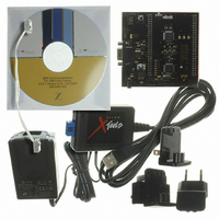
Z8F16800144ZCOG Zilog, Z8F16800144ZCOG Datasheet - Page 138

Z8F16800144ZCOG
Manufacturer Part Number
Z8F16800144ZCOG
Description
KIT DEV FOR Z8F642 MCU 44 PIN
Manufacturer
Zilog
Series
Z8 Encore!®r
Type
MCUr
Specifications of Z8F16800144ZCOG
Contents
Hardware, Software and Documentation
For Use With/related Products
Z8F642
For Use With
269-4661 - KIT ACC ETHERNET SMART CABLE
Lead Free Status / RoHS Status
Lead free / RoHS Compliant
Other names
269-4678
- Current page: 138 of 399
- Download datasheet (19Mb)
Low-Power Modes
Multi-Channel Timer Applications Examples
PS025011-1010
Capture/Compare Channel Interrupt
Operation in HALT Mode
Operation in STOP Mode
Power Reduction During Operation
PWM Programmable Deadband Generation
Multiple Timer Intervals Generation
A channel interrupt is generated whenever there is a successful Capture/Compare Event
on the Timer Channel and the associated CHIEN bit is set.
When the eZ8 CPU is operating in HALT mode, the Multi-Channel Timer will continue to
operate if enabled. To minimize current in HALT mode, the Multi-Channel Timer must be
disabled by clearing the TEN control bit.
When the eZ8 CPU is operating in STOP mode, the Multi-Channel Timer ceases to
operate as the system clock is stopped. The registers are not reset and operation will
resume once Stop Mode Recovery occurs.
Deassertion of the TEN bit will inhibit clocking of the entire Multi-Channel Timer block.
Deassertion of the CHEN bit of individual channels will inhibit clocking of channel
specific logic to minimize power consumption of unused channels. The CPU can still
read/write registers when the enable bit(s) are deasserted.
The count up/down mode supports motor control applications that require dead time
between output signals.
channels operating in count up/down mode.
Figure 18
timer is in Count Modulo mode with reload =
Continuous Compare operation. After every channel compare interrupt, the channel
Capture/Compare registers are updated in the interrupt service routine by adding a
constant equal to the time interval required. This operation requires that the CHUE bit
(Channel Update Enable) must be set in channels 0 and 1 so that writes to the
Capture/Compare registers take affect immediately.
on page 125 displays generation of two constant time intervals t0 and t1. The
Figure 17
P R E L I M I N A R Y
on page 125 displays dead time generation between two
FFFFH
. Channels 0 and 1 are set up for
Z8 Encore! XP
Product Specification
Multi-Channel Timer
®
F1680 Series
124
Related parts for Z8F16800144ZCOG
Image
Part Number
Description
Manufacturer
Datasheet
Request
R

Part Number:
Description:
Communication Controllers, ZILOG INTELLIGENT PERIPHERAL CONTROLLER (ZIP)
Manufacturer:
Zilog, Inc.
Datasheet:

Part Number:
Description:
KIT DEV FOR Z8 ENCORE 16K TO 64K
Manufacturer:
Zilog
Datasheet:

Part Number:
Description:
KIT DEV Z8 ENCORE XP 28-PIN
Manufacturer:
Zilog
Datasheet:

Part Number:
Description:
DEV KIT FOR Z8 ENCORE 8K/4K
Manufacturer:
Zilog
Datasheet:

Part Number:
Description:
KIT DEV Z8 ENCORE XP 28-PIN
Manufacturer:
Zilog
Datasheet:

Part Number:
Description:
DEV KIT FOR Z8 ENCORE 4K TO 8K
Manufacturer:
Zilog
Datasheet:

Part Number:
Description:
CMOS Z8 microcontroller. ROM 16 Kbytes, RAM 256 bytes, speed 16 MHz, 32 lines I/O, 3.0V to 5.5V
Manufacturer:
Zilog, Inc.
Datasheet:

Part Number:
Description:
Low-cost microcontroller. 512 bytes ROM, 61 bytes RAM, 8 MHz
Manufacturer:
Zilog, Inc.
Datasheet:

Part Number:
Description:
Z8 4K OTP Microcontroller
Manufacturer:
Zilog, Inc.
Datasheet:

Part Number:
Description:
CMOS SUPER8 ROMLESS MCU
Manufacturer:
Zilog, Inc.
Datasheet:

Part Number:
Description:
SL1866 CMOSZ8 OTP Microcontroller
Manufacturer:
Zilog, Inc.
Datasheet:

Part Number:
Description:
SL1866 CMOSZ8 OTP Microcontroller
Manufacturer:
Zilog, Inc.
Datasheet:

Part Number:
Description:
OTP (KB) = 1, RAM = 125, Speed = 12, I/O = 14, 8-bit Timers = 2, Comm Interfaces Other Features = Por, LV Protect, Voltage = 4.5-5.5V
Manufacturer:
Zilog, Inc.
Datasheet:

Part Number:
Description:
Manufacturer:
Zilog, Inc.
Datasheet:


