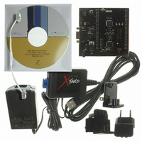
Z8F16800144ZCOG Zilog, Z8F16800144ZCOG Datasheet - Page 243

Z8F16800144ZCOG
Manufacturer Part Number
Z8F16800144ZCOG
Description
KIT DEV FOR Z8F642 MCU 44 PIN
Manufacturer
Zilog
Series
Z8 Encore!®r
Type
MCUr
Specifications of Z8F16800144ZCOG
Contents
Hardware, Software and Documentation
For Use With/related Products
Z8F642
For Use With
269-4661 - KIT ACC ETHERNET SMART CABLE
Lead Free Status / RoHS Status
Lead free / RoHS Compliant
Other names
269-4678
- Current page: 243 of 399
- Download datasheet (19Mb)
PS025011-1010
Slave 7-Bit Address Recognition Mode
If
or SLAVE 7-bit address mode, the hardware detects a match to the 7-bit slave address
defined in the I2CSLVAD Register and generates the slave address match interrupt (the
SAM
the Acknowledge phase with the value in the
Slave 10-Bit Address Recognition Mode
If
or SLAVE 10-bit address mode, the hardware detects a match to the 10-bit slave address
defined in the I2CMODE and I2CSLVAD registers and generates the slave address match
interrupt (the
responds during the Acknowledge phase with the value in the
Register.
General Call and Start Byte Address Recognition
If
MASTER/SLAVE or SLAVE in either 7- or 10-bit address modes, the hardware detects a
match to the General Call Address or the START byte and generates the slave address
match interrupt. A General Call Address is a 7-bit address of all 0’s with the R/W bit = 0.
A START byte is a 7-bit address of all 0’s with the R/W bit = 1. The
are set in the I2CISTAT Register. The
General Call Address from a START byte which is cleared to 0 for a General Call
Address). For a General Call Address, the I
the address acknowledge phase with the value in the
If the software is set to process the data bytes associated with the
can optionally be set following the
received data byte before deciding to set or clear the
acknowledged—a requirement of the I
Software Address Recognition
To disable hardware address recognition, the
reception of the address byte(s). When
interrupt (
and determine whether to set or clear the
Acknowledge phase until the software responds by writing to the I2CCTL Register. The
value written to the
SCL. The
bit is updated based on the first address byte.
IRM
IRM
GCE
bit = 1 in the I2CISTAT Register). The I
= 0 during the address phase and the controller is configured for MASTER/SLAVE
= 0 during the address phase and the controller is configured for MASTER/SLAVE
= 1 and
RDRF
SAM
SAM
IRM
and
= 1 in the I2CISTAT Register). The software must examine each byte
bit = 1 in the I2CISTAT Register). The I
NAK
= 0 during the address phase, and the controller is configured for
GCA
bit is used by the controller to drive the I
bits are not set when
P R E L I M I N A R Y
SAM
RD
2
IRM
C specification.
interrupt to allow the software to examine each
NAK
bit in the I2CISTAT Register distinguishes a
2
= 1, each received byte generates a receive
C controller automatically responds during
2
IRM
IRM
NAK
C controller automatically responds during
bit. The slave holds SCL Low during the
bit must be set to 1 prior to the
= 1 during the address phase, but the
bit of the I2CCTL Register.
NAK
NAK
Z8 Encore! XP
bit of the I2CCTL Register.
bit. A START byte will not be
2
C controller automatically
NAK
2
Product Specification
I2C Master/Slave Controller
C bus, then releasing the
GCA
bit of the I2CCTL
SAM
bit, the
®
and
F1680 Series
GCA
IRM
bits
bit
RD
229
Related parts for Z8F16800144ZCOG
Image
Part Number
Description
Manufacturer
Datasheet
Request
R

Part Number:
Description:
Communication Controllers, ZILOG INTELLIGENT PERIPHERAL CONTROLLER (ZIP)
Manufacturer:
Zilog, Inc.
Datasheet:

Part Number:
Description:
KIT DEV FOR Z8 ENCORE 16K TO 64K
Manufacturer:
Zilog
Datasheet:

Part Number:
Description:
KIT DEV Z8 ENCORE XP 28-PIN
Manufacturer:
Zilog
Datasheet:

Part Number:
Description:
DEV KIT FOR Z8 ENCORE 8K/4K
Manufacturer:
Zilog
Datasheet:

Part Number:
Description:
KIT DEV Z8 ENCORE XP 28-PIN
Manufacturer:
Zilog
Datasheet:

Part Number:
Description:
DEV KIT FOR Z8 ENCORE 4K TO 8K
Manufacturer:
Zilog
Datasheet:

Part Number:
Description:
CMOS Z8 microcontroller. ROM 16 Kbytes, RAM 256 bytes, speed 16 MHz, 32 lines I/O, 3.0V to 5.5V
Manufacturer:
Zilog, Inc.
Datasheet:

Part Number:
Description:
Low-cost microcontroller. 512 bytes ROM, 61 bytes RAM, 8 MHz
Manufacturer:
Zilog, Inc.
Datasheet:

Part Number:
Description:
Z8 4K OTP Microcontroller
Manufacturer:
Zilog, Inc.
Datasheet:

Part Number:
Description:
CMOS SUPER8 ROMLESS MCU
Manufacturer:
Zilog, Inc.
Datasheet:

Part Number:
Description:
SL1866 CMOSZ8 OTP Microcontroller
Manufacturer:
Zilog, Inc.
Datasheet:

Part Number:
Description:
SL1866 CMOSZ8 OTP Microcontroller
Manufacturer:
Zilog, Inc.
Datasheet:

Part Number:
Description:
OTP (KB) = 1, RAM = 125, Speed = 12, I/O = 14, 8-bit Timers = 2, Comm Interfaces Other Features = Por, LV Protect, Voltage = 4.5-5.5V
Manufacturer:
Zilog, Inc.
Datasheet:

Part Number:
Description:
Manufacturer:
Zilog, Inc.
Datasheet:


