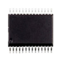
ST52F513G3M6 STMicroelectronics, ST52F513G3M6 Datasheet - Page 53

ST52F513G3M6
Manufacturer Part Number
ST52F513G3M6
Description
Manufacturer
STMicroelectronics
Datasheet
1.ST52F513G3M6.pdf
(136 pages)
Specifications of ST52F513G3M6
Cpu Family
ST52
Device Core Size
8b
Frequency (max)
20MHz
Interface Type
I2C/SCI/SPI
Program Memory Type
Flash
Program Memory Size
8KB
Total Internal Ram Size
256Byte
# I/os (max)
22
Number Of Timers - General Purpose
2
Operating Supply Voltage (typ)
3.3/5V
Operating Supply Voltage (max)
5.5V
Operating Supply Voltage (min)
2.7V
On-chip Adc
8-chx10-bit
Instruction Set Architecture
CISC
Operating Temp Range
-40C to 85C
Operating Temperature Classification
Industrial
Mounting
Surface Mount
Pin Count
28
Package Type
SO
Lead Free Status / Rohs Status
Compliant
Available stocks
Company
Part Number
Manufacturer
Quantity
Price
Part Number:
ST52F513G3M6
Manufacturer:
ST
Quantity:
20 000
Part Number:
ST52F513G3M6TR
Manufacturer:
ST
Quantity:
20 000
7.5 Alternate Functions
The Alternate Function allows the pins to be
connected with the peripheral signals or NMI. Not
all
associated.
A Configuration Register (PORT_x_AF) for each
Port is used to switch from the Digital I/O function
or the Alternate Function.
Some pins can have two Alternate Functions: one
input function and one output function. To switch
between the two functions, the PORT_x_AF must
be configured in Alternate Function mode and the
PORT_x_DDR Configuration Register must be
switched in Input mode or in Output mode.
NMI is considered an Alternate Function. For this
reason an NMI interrupt request can’t be
generated unless the PA7 pin is configured in
Alternate Function and in one of the Input modes.
Figure 7.3 Port Pin Architecture
Port
ALTERNATE
CONF. REG.
CONF. REG.
CONF. REG.
CONF. REG.
INTERRUPT
FUNCTION
POLARITY
REGISTER
pins
FILE
have
IRQ
FF
an
Alternate
D
E
C
O
D
E
R
REGISTER
EN
SEL
PU
INT
TO INPUT
Function
When an on-chip peripheral is configured to use a
pin, the correct I/O mode of the related pin should
be selected by selecting one of the appropriate
modes. See the Registers description in order to
obtain the right configurations.Some peripherals,
as for example the I
pin configuration according to the current function,
overriding the user configuration.
7.6 Register Description
In order to configure the Port’s pins, the three
Configuration
PORT_x_OR
configured. The combination of these three
registers
according to the scheme shown in
In order to select between the digital functions or
Alternate functions PORT_x_AF register must be
configured. Each bit of the configuration registers
configures the pin of the corresponding position
(example: PORT_A_DDR bit 5 configures the pin
PA5).
DATA
ENABLE
determine
and
Registers
2
C peripheral, directly drive the
PORT_x_DDR
ST52510xx ST52513xx
the
Vdd
pin’s
PORT_x_PULLUP,
Table
configuration,
must
PORT PIN
DIGITAL
7.1.
53/136
be


