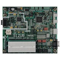
LFEBS12UB Freescale Semiconductor, LFEBS12UB Datasheet - Page 787

LFEBS12UB
Manufacturer Part Number
LFEBS12UB
Description
KIT STUDENT LEARNING S12 DG128
Manufacturer
Freescale Semiconductor
Specifications of LFEBS12UB
Architecture
8/16-bit
Code Gen Tools Included
Code Warrior
Silicon Manufacturer
Freescale
Core Architecture
S12
Core Sub-architecture
S12
Silicon Core Number
MC9S12
Silicon Family Name
S12D
Kit Contents
HCS12 DG128 Learning Kit
Rohs Compliant
Yes
Lead Free Status / RoHS Status
Lead free / RoHS Compliant
- Current page: 787 of 1328
- Download datasheet (9Mb)
21.4.7.3
Stop mode is dependent on the system. The SPI enters stop mode when the module clock is disabled (held
high or low). If the SPI is in master mode and exchanging data when the CPU enters stop mode, the
transmission is frozen until the CPU exits stop mode. After stop, data to and from the external SPI is
exchanged correctly. In slave mode, the SPI will stay synchronized with the master.
The stop mode is not dependent on the SPISWAI bit.
21.4.7.4
The reset values of registers and signals are described in
Definition”, which details the registers and their bit fields.
21.4.7.5
The SPI only originates interrupt requests when SPI is enabled (SPE bit in SPICR1 set). The following is
a description of how the SPI makes a request and how the MCU should acknowledge that request. The
interrupt vector offset and interrupt priority are chip dependent.
The interrupt flags MODF, SPIF, and SPTEF are logically ORed to generate an interrupt request.
21.4.7.5.1
MODF occurs when the master detects an error on the SS pin. The master SPI must be configured for the
MODF feature (see
changed:
The MODF interrupt is reflected in the status register MODF flag. Clearing the flag will also clear the
interrupt. This interrupt will stay active while the MODF flag is set. MODF has an automatic clearing
process which is described in
Freescale Semiconductor
Because of an order from the United States International Trade Commission, BGA-packaged product lines and partnumbers
indicated here currently are not available from Freescale for import or sale in the United States prior to September 2010
•
•
•
If a data transmission occurs in slave mode after reset without a write to SPIDR, it will transmit
garbage, or the data last received from the master before the reset.
Reading from the SPIDR after reset will always read zeros.
MSTR = 0, The master bit in SPICR1 resets.
SPI in Stop Mode
Reset
Interrupts
Care must be taken when expecting data from a master while the slave is in
wait or stop mode. Even though the shift register will continue to operate,
the rest of the SPI is shut down (i.e., a SPIF interrupt will not be generated
until exiting stop or wait mode). Also, the byte from the shift register will
not be copied into the SPIDR register until after the slave SPI has exited wait
or stop mode. In slave mode, a received byte pending in the receive shift
register will be lost when entering wait or stop mode. An SPIF flag and
SPIDR copy is generated only if wait mode is entered or exited during a
tranmission. If the slave enters wait mode in idle mode and exits wait mode
in idle mode, neither a SPIF nor a SPIDR copy will occur.
MODF
Table
21-3). After MODF is set, the current transfer is aborted and the following bit is
Section 21.3.2.4, “SPI Status Register
MC9S12XE-Family Reference Manual Rev. 1.23
NOTE
Section 21.3, “Memory Map and Register
Chapter 21 Serial Peripheral Interface (S12SPIV5)
(SPISR)”.
787
Related parts for LFEBS12UB
Image
Part Number
Description
Manufacturer
Datasheet
Request
R
Part Number:
Description:
Manufacturer:
Freescale Semiconductor, Inc
Datasheet:
Part Number:
Description:
Manufacturer:
Freescale Semiconductor, Inc
Datasheet:
Part Number:
Description:
Manufacturer:
Freescale Semiconductor, Inc
Datasheet:
Part Number:
Description:
Manufacturer:
Freescale Semiconductor, Inc
Datasheet:
Part Number:
Description:
Manufacturer:
Freescale Semiconductor, Inc
Datasheet:
Part Number:
Description:
Manufacturer:
Freescale Semiconductor, Inc
Datasheet:
Part Number:
Description:
Manufacturer:
Freescale Semiconductor, Inc
Datasheet:
Part Number:
Description:
Manufacturer:
Freescale Semiconductor, Inc
Datasheet:
Part Number:
Description:
Manufacturer:
Freescale Semiconductor, Inc
Datasheet:
Part Number:
Description:
Manufacturer:
Freescale Semiconductor, Inc
Datasheet:
Part Number:
Description:
Manufacturer:
Freescale Semiconductor, Inc
Datasheet:
Part Number:
Description:
Manufacturer:
Freescale Semiconductor, Inc
Datasheet:
Part Number:
Description:
Manufacturer:
Freescale Semiconductor, Inc
Datasheet:
Part Number:
Description:
Manufacturer:
Freescale Semiconductor, Inc
Datasheet:
Part Number:
Description:
Manufacturer:
Freescale Semiconductor, Inc
Datasheet:


