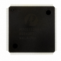
PI7C8152BMAE Pericom Semiconductor, PI7C8152BMAE Datasheet - Page 22

PI7C8152BMAE
Manufacturer Part Number
PI7C8152BMAE
Description
IC PCI-PCI BRIDGE 2PORT 160-MQFP
Manufacturer
Pericom Semiconductor
Datasheet
1.PI7C8152AMAE.pdf
(90 pages)
Specifications of PI7C8152BMAE
Applications
*
Interface
*
Voltage - Supply
*
Package / Case
160-MQFP, 160-PQFP
Mounting Type
Surface Mount
Maximum Operating Temperature
+ 85 C
Minimum Operating Temperature
0 C
Mounting Style
SMD/SMT
Operating Supply Voltage
3 V to 3.6 V
Supply Current (max)
246 mA
Lead Free Status / RoHS Status
Lead free / RoHS Compliant
Available stocks
Company
Part Number
Manufacturer
Quantity
Price
Company:
Part Number:
PI7C8152BMAE
Manufacturer:
PERICOM
Quantity:
748
Part Number:
PI7C8152BMAE
Manufacturer:
PERICOM
Quantity:
20 000
3.6.4
3.6.5
Table 3-3 WRITE TRANSACTION DISCONNECT ADDRESS BOUNDARIES
information about how PI7C8152x responds to target termination during delayed write
transactions.
PI7C8152x implements a discard timer that starts counting when the delayed write
completion is at the head of the delayed transaction completion queue. The initial value of
this timer can be set to the retry counter register offset 78h.
If the initiator does not repeat the delayed write transaction before the discard
timer expires, PI7C8152x discards the delayed write completion from the delayed
transaction completion queue. PI7C8152x also conditionally asserts P_SERR_L
(see Section 6.4).
WRITE TRANSACTION ADDRESS BOUNDARIES
PI7C8152x imposes internal address boundaries when accepting write data.
The aligned address boundaries are used to prevent PI7C8152x from continuing
a transaction over a device address boundary and to provide an upper limit on maximum
latency. PI7C78152 returns a target disconnect to the initiator when it reaches the aligned
address boundaries under conditions shown in Table 3-3.
BUFFERING MULTIPLE WRITE TRANSACTIONS
PI7C8152x continues to accept posted memory write transactions as long as space for at
least one DWORD of data in the posted write data buffer remains. If the posted write data
buffer fills before the initiator terminates the write transaction, PI7C8152x returns a target
disconnect to the initiator.
Delayed write transactions are accepted as long as at least one open entry in
the delayed transaction queue exists. Therefore, several posted and delayed write
transactions can exist in data buffers at the same time. See Chapter 5 for information about
how multiple posted and delayed write transactions are ordered.
Note 1. Memory write disconnect control bit is bit 1 of the chip control register at offset 40h in the
configuration space.
Type of Transaction
Delayed Write
Posted Memory Write
Posted Memory Write
Posted Memory Write and
Invalidate
Posted Memory Write and
Invalidate
Posted Memory Write and
Invalidate
bit = 0
Condition
All
Memory write disconnect control
Memory write disconnect control
bit = 1
Cache line size ≠ 1, 2, 4, 8, 16
Cache line size = 1, 2, 4, 8
Cache line size = 16
Page 22 of 90
(1)
(1)
2-PORT PCI-TO-PCI BRIDGE
October 16, 2003 – Revision 1.11
Aligned Address Boundary
Disconnects after one data transfer
4KB aligned address boundary
Disconnects at cache line boundary
4KB aligned address boundary
Cache line boundary if posted memory
write data FIFO does not have enough
space for the next cache line
16-DWORD aligned address boundary
ADVANCE INFORMATION
PI7C8152A & PI7C8152B


