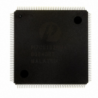
PI7C8152BMAE Pericom Semiconductor, PI7C8152BMAE Datasheet - Page 64

PI7C8152BMAE
Manufacturer Part Number
PI7C8152BMAE
Description
IC PCI-PCI BRIDGE 2PORT 160-MQFP
Manufacturer
Pericom Semiconductor
Datasheet
1.PI7C8152AMAE.pdf
(90 pages)
Specifications of PI7C8152BMAE
Applications
*
Interface
*
Voltage - Supply
*
Package / Case
160-MQFP, 160-PQFP
Mounting Type
Surface Mount
Maximum Operating Temperature
+ 85 C
Minimum Operating Temperature
0 C
Mounting Style
SMD/SMT
Operating Supply Voltage
3 V to 3.6 V
Supply Current (max)
246 mA
Lead Free Status / RoHS Status
Lead free / RoHS Compliant
Available stocks
Company
Part Number
Manufacturer
Quantity
Price
Company:
Part Number:
PI7C8152BMAE
Manufacturer:
PERICOM
Quantity:
748
Part Number:
PI7C8152BMAE
Manufacturer:
PERICOM
Quantity:
20 000
9.4
10
Table 10-1 POWER MANAGEMENT TRANSITIONS
P_CLK is the input source for the primary clock and S_CLKIN is the input source for the
secondary clock. The S_CLKOUT[4:0] outputs cannot be used for any external secondary
bus devices in asynchronous mode. Instead, devices on the secondary bus must utilize the
same clock that is used for S_CLKIN.
SYNCHRONOUS MODE
In synchronous mode, the primary bus and the secondary bus must both be running at the
same frequency. The S_CLKOUT[4:0] outputs are derived directly from P_CLK and
S_CLKOUT[4] is used as a feedback to S_CLKIN. PI7C8152x will not operate at split
frequencies (primary different than secondary) in synchronous mode. The frequency on
the secondary bus will be the same as the frequency on the primary bus unless
asynchronous mode is utilized.
PCI POWER MANAGEMENT
PI7C8152x incorporates functionality that meets the requirements of the PCI Power
Management Specification, Revision 1.1. These features include:
!
!
!
!
!
Table 10-1 shows the states and related actions that PI7C8152x performs during power
management transitions. (No other transactions are permitted.)
D0
D0
D0
D0
D3hot
D3hot
D3cold
Current Status
PCI Power Management registers using the Enhanced Capabilities Port (ECP) address
mechanism
Support for D0, D1, D2, D3
Support for D0, D1, D2, D3
behind the bridge
Support of the B2 secondary bus power state when in the D2 or D3
management state
Support of the B1 secondary bus power state when in the D1 power management state
D3cold
D3hot
D2
D1
D0
D3cold
D0
Next State
Page 64 of 90
hot
hot
Power has been removed from PI7C8152x. A power-up reset must be
performed to bring PI7C8152x to D0.
If enabled to do so by the BPCCE pin, PI7C8152x will disable the
secondary clocks and drive them LOW.
If enabled to do so by the BPCEE pin, PI7C8152x will disable the
secondary clocks and driver them LOW.
PI7C8152x only accepts Type 0 configuration cycles on the primary
and ignores all others.
PI7C8152x enables secondary clock outputs and performs an internal
chip reset. Signal S_RST_L will not be asserted. All registers will
be returned to the reset values and buffers will be cleared.
Power has been removed from PI7C8152x. A power-up reset must
be performed to bring PI7C8152x to D0.
Power-up reset. PI7C8152x performs the standard power-up reset
functions as described in Section 11.
and D3
, and D3
cold
cold
power management states
power management states for devices
2-PORT PCI-TO-PCI BRIDGE
October 16, 2003 – Revision 1.11
ADVANCE INFORMATION
Action
PI7C8152A & PI7C8152B
hot
power


