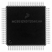
MC9S12XDT256CAA Freescale Semiconductor, MC9S12XDT256CAA Datasheet - Page 726

MC9S12XDT256CAA
Manufacturer Part Number
MC9S12XDT256CAA
Description
IC MCU 256K FLASH 80-QFP
Manufacturer
Freescale Semiconductor
Series
HCS12r
Datasheet
1.MC9S12XD64CAA.pdf
(1348 pages)
Specifications of MC9S12XDT256CAA
Core Processor
HCS12X
Core Size
16-Bit
Speed
80MHz
Connectivity
CAN, EBI/EMI, I²C, IrDA, LIN, SCI, SPI
Peripherals
LVD, POR, PWM, WDT
Number Of I /o
59
Program Memory Size
256KB (256K x 8)
Program Memory Type
FLASH
Eeprom Size
4K x 8
Ram Size
16K x 8
Voltage - Supply (vcc/vdd)
2.35 V ~ 5.5 V
Data Converters
A/D 8x10b
Oscillator Type
External
Operating Temperature
-40°C ~ 85°C
Package / Case
80-QFP
Processor Series
S12XD
Core
HCS12
Data Bus Width
16 bit
Data Ram Size
16 KB
Interface Type
CAN/I2C/SCI/SPI
Maximum Clock Frequency
40 MHz
Number Of Programmable I/os
59
Number Of Timers
12
Maximum Operating Temperature
+ 85 C
Mounting Style
SMD/SMT
3rd Party Development Tools
EWHCS12
Development Tools By Supplier
EVB9S12XDP512E
Minimum Operating Temperature
- 40 C
On-chip Adc
8-ch x 10-bit
Lead Free Status / RoHS Status
Lead free / RoHS Compliant
Available stocks
Company
Part Number
Manufacturer
Quantity
Price
Company:
Part Number:
MC9S12XDT256CAA
Manufacturer:
Freescale Semiconductor
Quantity:
10 000
Company:
Part Number:
MC9S12XDT256CAAR
Manufacturer:
Freescale Semiconductor
Quantity:
10 000
- Current page: 726 of 1348
- Download datasheet (8Mb)
Chapter 19 S12X Debug (S12XDBGV2) Module
19.4.5.3.3
Trace Buffer Reset State
The trace buffer contents are not initialized by a system reset. Thus should a system reset occur, the trace
session information from immediately before the reset occurred can be read out. The DBGCNT bits are
not cleared by a system reset. Thus should a reset occur, the number of valid lines in the trace buffer is
indicated by DBGCNT. The internal pointer to the current trace buffer address is initialized by unlocking
the trace buffer thus points to the oldest valid data even if a reset occurred during the tracing session.
Generally debugging occurrences of system resets is best handled using mid or end-trigger alignment since
the reset may occur before the trace trigger, which in the begin-trigger alignment case means no
information would be stored in the trace buffer.
19.4.6
Tagging
A tag follows program information as it advances through the instruction queue. When a tagged instruction
reaches the head of the queue a tag hit occurs and triggers the state sequencer.
Each comparator control register features a TAG bit, which controls whether the comparator match will
cause a trigger immediately or tag the opcode at the matched address. If a comparator is enabled for tagged
comparisons, the address stored in the comparator match address registers must be an opcode address for
the trigger to occur.
Both CPU and XGATE opcodes can be tagged with the comparator register TAG bits.
Using a begin-aligned trigger together with tagging, if the tagged instruction is about to be executed then
the transition to the next state sequencer state occurs. If the transition is to the final state, tracing is started.
Only upon completion of the tracing session can a breakpoint be generated. Similarly using a mid-aligned
trigger with tagging, if the tagged instruction is about to be executed then the trace is continued for another
32 lines. Upon tracing completion the breakpoint is generated. Using an end-aligned trigger, when the
tagged instruction is about to be executed and the next transition is to final state then a breakpoint is
generated immediately, before the tagged instruction is carried out.
R/W monitoring is not useful for tagged operations since the trigger occurs based on the tagged opcode
reaching the execution stage of the instruction queue. Similarly access size (SZ) monitoring and data bus
monitoring is not useful if tagged triggering is selected, since the tag is attached to the opcode at the
matched address and is not dependent on the data bus nor on the size of access. Thus these bits are ignored
if tagged triggering is selected.
When configured for range comparisons and tagging, the ranges are accurate only to word boundaries.
CPU tagging is disabled when the BDM becomes active. Conversely, BDM firmware commands are not
processed while tagging is active. XGATE tagging is possible when the BDM is active.
MC9S12XDP512 Data Sheet, Rev. 2.21
728
Freescale Semiconductor
Related parts for MC9S12XDT256CAA
Image
Part Number
Description
Manufacturer
Datasheet
Request
R

Part Number:
Description:
16-BIT MICROPROCESSOR FAMILY
Manufacturer:
FREESCALE [Freescale Semiconductor, Inc]
Datasheet:
Part Number:
Description:
Manufacturer:
Freescale Semiconductor, Inc
Datasheet:
Part Number:
Description:
Manufacturer:
Freescale Semiconductor, Inc
Datasheet:
Part Number:
Description:
Manufacturer:
Freescale Semiconductor, Inc
Datasheet:
Part Number:
Description:
Manufacturer:
Freescale Semiconductor, Inc
Datasheet:
Part Number:
Description:
Manufacturer:
Freescale Semiconductor, Inc
Datasheet:
Part Number:
Description:
Manufacturer:
Freescale Semiconductor, Inc
Datasheet:
Part Number:
Description:
Manufacturer:
Freescale Semiconductor, Inc
Datasheet:
Part Number:
Description:
Manufacturer:
Freescale Semiconductor, Inc
Datasheet:
Part Number:
Description:
Manufacturer:
Freescale Semiconductor, Inc
Datasheet:
Part Number:
Description:
Manufacturer:
Freescale Semiconductor, Inc
Datasheet:
Part Number:
Description:
Manufacturer:
Freescale Semiconductor, Inc
Datasheet:
Part Number:
Description:
Manufacturer:
Freescale Semiconductor, Inc
Datasheet:
Part Number:
Description:
Manufacturer:
Freescale Semiconductor, Inc
Datasheet:
Part Number:
Description:
Manufacturer:
Freescale Semiconductor, Inc
Datasheet:


