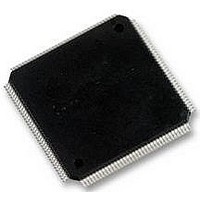
LCMXO2280C-5TN144C LATTICE SEMICONDUCTOR, LCMXO2280C-5TN144C Datasheet - Page 199

LCMXO2280C-5TN144C
Manufacturer Part Number
LCMXO2280C-5TN144C
Description
MACHXO PLD FLASH, SCRAM 1.8V, SMD
Manufacturer
LATTICE SEMICONDUCTOR
Series
MachXOr
Datasheet
1.LCMXO1200C-5TN144C.pdf
(244 pages)
Specifications of LCMXO2280C-5TN144C
Cpld Type
FLASH
No. Of Macrocells
1140
No. Of I/o's
113
Propagation Delay
3.6ns
Global Clock Setup Time
1.1ns
Frequency
600MHz
Supply Voltage Range
1.71V To 3.465V
Operating
RoHS Compliant
Available stocks
Company
Part Number
Manufacturer
Quantity
Price
Company:
Part Number:
LCMXO2280C-5TN144C
Manufacturer:
Lattice Semiconductor Corporation
Quantity:
10 000
Part Number:
LCMXO2280C-5TN144C
Manufacturer:
LATTICE/莱迪斯
Quantity:
20 000
- Current page: 199 of 244
- Download datasheet (9Mb)
Power Estimation and Management
Lattice Semiconductor
for MachXO Devices
Figure 11-15. Importing Trace Report File in the Existing Project in the Power Calculator
Activity Factor and Toggle Rate
Activity Factor% (or AF%) is defined as the percentage of frequency (or time) that a signal is active or toggling of
the output. Most of the resources associated with a clock domain are running or toggling at some percentage of the
frequency at which the clock is running. Users are required to provide this value as a percentage under the AF%
column in the Power Calculator tool.
Another term used for I/Os is the I/O Toggle Rate or the I/O Toggle Frequency. The AF% is applicable to the PFU,
routing and memory read write ports, etc. The activity of I/Os is determined by the signals provided by the user (in
the case of inputs) or as an output of the design (in the case of outputs). So, the rates at which I/Os toggle defines
their activity. The Toggle Rate (or TR) in MHz of the output is defined as:
Toggle Rate (MHz) = 1/2 * f
* AF%
MAX
Users are required to provide the TR (MHz) value for the I/O instead of providing the frequency and AF% in case of
other resources. The AF can be calculated for each routing resource, output or PFU, however it involves long calcu-
lations. The general recommendation of a design occupying roughly 30% to 70% of the device is that the AF%
used can be between 15% to 25%. This is an average value that can be seen most of the design. The accurate
value of an AF depends upon clock frequency, stimulus to the design and the final output.
Ambient and Junction Temperature and Airflow
A common method of characterizing a packaged device’s thermal performance is with Thermal Resistance, . For
a semiconductor device, thermal resistance indicates the steady state temperature rise of the die junction above a
given reference for each watt of power (heat) dissipated at the die surface. Its units are °C/W.
11-16
Related parts for LCMXO2280C-5TN144C
Image
Part Number
Description
Manufacturer
Datasheet
Request
R
Part Number:
Description:
IC, CPLD, FLASH, 2280 MACROCELL FTBGA256
Manufacturer:
LATTICE SEMICONDUCTOR
Part Number:
Description:
CPLD MachXO Family 1140 Macro Cells 1.8V/2.5V/3.3V 324-Pin FTBGA Tray
Manufacturer:
LATTICE SEMICONDUCTOR
Datasheet:

Part Number:
Description:
Microcontroller Modules & Accessories MACHXO CNRL EVB
Manufacturer:
Lattice
Datasheet:

Part Number:
Description:
IC, CPLD, FLASH, 2280 MACROCELL, TQFP144
Manufacturer:
LATTICE SEMICONDUCTOR

Part Number:
Description:
MACHXO PLD FLASH, SCRAM 1.8V, SMD
Manufacturer:
LATTICE SEMICONDUCTOR
Datasheet:
Part Number:
Description:
CPLD MachXO Family 1140 Macro Cells 1.8V/2.5V/3.3V 256-Pin FTBGA Tray
Manufacturer:
LATTICE SEMICONDUCTOR
Datasheet:
Part Number:
Description:
CPLD MachXO Family 1140 Macro Cells 1.8V/2.5V/3.3V 324-Pin FTBGA Tray
Manufacturer:
LATTICE SEMICONDUCTOR
Datasheet:
Part Number:
Description:
CPLD MachXO Family 1140 Macro Cells 1.8V/2.5V/3.3V 100-Pin TQFP Tray
Manufacturer:
LATTICE SEMICONDUCTOR
Datasheet:
Part Number:
Description:
ISPLSI2032-80LT44Lattice Semiconductor [In-System Programmable High Density PLD]
Manufacturer:
Lattice Semiconductor Corp.
Datasheet:
Part Number:
Description:
IC PROGRAMMED LATTICE GAL 16V8
Manufacturer:
Lattice Semiconductor Corp.
Datasheet:
Part Number:
Description:
357-036-542-201 CARDEDGE 36POS DL .156 BLK LOPRO
Manufacturer:
Lattice Semiconductor Corp.
Datasheet:
Part Number:
Description:
357-036-542-201 CARDEDGE 36POS DL .156 BLK LOPRO
Manufacturer:
Lattice Semiconductor Corp.
Datasheet:
Part Number:
Description:
357-036-542-201 CARDEDGE 36POS DL .156 BLK LOPRO
Manufacturer:
Lattice Semiconductor Corp.
Datasheet:
Part Number:
Description:
357-036-542-201 CARDEDGE 36POS DL .156 BLK LOPRO
Manufacturer:
Lattice Semiconductor Corp.
Datasheet:


