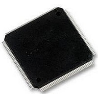
LCMXO2280C-5TN144C LATTICE SEMICONDUCTOR, LCMXO2280C-5TN144C Datasheet - Page 208

LCMXO2280C-5TN144C
Manufacturer Part Number
LCMXO2280C-5TN144C
Description
MACHXO PLD FLASH, SCRAM 1.8V, SMD
Manufacturer
LATTICE SEMICONDUCTOR
Series
MachXOr
Datasheet
1.LCMXO1200C-5TN144C.pdf
(244 pages)
Specifications of LCMXO2280C-5TN144C
Cpld Type
FLASH
No. Of Macrocells
1140
No. Of I/o's
113
Propagation Delay
3.6ns
Global Clock Setup Time
1.1ns
Frequency
600MHz
Supply Voltage Range
1.71V To 3.465V
Operating
RoHS Compliant
Available stocks
Company
Part Number
Manufacturer
Quantity
Price
Company:
Part Number:
LCMXO2280C-5TN144C
Manufacturer:
Lattice Semiconductor Corporation
Quantity:
10 000
Part Number:
LCMXO2280C-5TN144C
Manufacturer:
LATTICE/莱迪斯
Quantity:
20 000
- Current page: 208 of 244
- Download datasheet (9Mb)
Lattice Semiconductor
Design Partitioning
By effectively partitioning the design, a designer can reduce overall run time and improve synthesis results. Here
are some recommendations for design partitioning.
Maintain Synchronous Sub-blocks by Registering All Outputs
It is suggested to arrange the design boundary such that the outputs in each block are registered. Registering out-
puts helps the synthesis tool to consider the implementation of the combinatorial logic and registers into the same
logic block. Registering outputs also makes the application of timing constraints easier since it eliminates possible
problems with logic optimization across design boundaries. Single clock is recommended for each synchronous
block because it significantly reduces the timing consideration in the block. It leaves the adjustment of the clock
relationships of the whole design at the top level of the hierarchy. Figure 13-1 shows an example of synchronous
blocks with registered outputs.
Figure 13-1. Synchronous Blocks with Registered Outputs
Keep Related Logic Together in the Same Block
Keeping related logic and sharable resources in the same block allows the sharing of common combinatorial terms
and arithmetic functions within the block. It also allows the synthesis tools to optimize the entire critical path in a
single operation. Since synthesis tools can only effectively handle optimization of certain amounts of logic, optimi-
zation of critical paths pending across the boundaries may not be optimal. Figure 13-2 shows an example of merg-
ing sharable resource in the same block.
Figure 13-2. Merge Sharable Resource in the Same Block
Separate Logic with Different Optimization Goals
Separating critical paths from non-critical paths may achieve efficient synthesis results. At the beginning of the proj-
ect, one should consider the design in terms of performance requirements and resource requirements. If there are
• Memory blocks should be kept separate from other code
A
A
A
A
B
B
B
B
MUX
MUX
+
+
13-2
HDL Synthesis Coding Guidelines
for Lattice Semiconductor FPGAs
C
C
+
Related parts for LCMXO2280C-5TN144C
Image
Part Number
Description
Manufacturer
Datasheet
Request
R
Part Number:
Description:
IC, CPLD, FLASH, 2280 MACROCELL FTBGA256
Manufacturer:
LATTICE SEMICONDUCTOR
Part Number:
Description:
CPLD MachXO Family 1140 Macro Cells 1.8V/2.5V/3.3V 324-Pin FTBGA Tray
Manufacturer:
LATTICE SEMICONDUCTOR
Datasheet:

Part Number:
Description:
Microcontroller Modules & Accessories MACHXO CNRL EVB
Manufacturer:
Lattice
Datasheet:

Part Number:
Description:
IC, CPLD, FLASH, 2280 MACROCELL, TQFP144
Manufacturer:
LATTICE SEMICONDUCTOR

Part Number:
Description:
MACHXO PLD FLASH, SCRAM 1.8V, SMD
Manufacturer:
LATTICE SEMICONDUCTOR
Datasheet:
Part Number:
Description:
CPLD MachXO Family 1140 Macro Cells 1.8V/2.5V/3.3V 256-Pin FTBGA Tray
Manufacturer:
LATTICE SEMICONDUCTOR
Datasheet:
Part Number:
Description:
CPLD MachXO Family 1140 Macro Cells 1.8V/2.5V/3.3V 324-Pin FTBGA Tray
Manufacturer:
LATTICE SEMICONDUCTOR
Datasheet:
Part Number:
Description:
CPLD MachXO Family 1140 Macro Cells 1.8V/2.5V/3.3V 100-Pin TQFP Tray
Manufacturer:
LATTICE SEMICONDUCTOR
Datasheet:
Part Number:
Description:
ISPLSI2032-80LT44Lattice Semiconductor [In-System Programmable High Density PLD]
Manufacturer:
Lattice Semiconductor Corp.
Datasheet:
Part Number:
Description:
IC PROGRAMMED LATTICE GAL 16V8
Manufacturer:
Lattice Semiconductor Corp.
Datasheet:
Part Number:
Description:
357-036-542-201 CARDEDGE 36POS DL .156 BLK LOPRO
Manufacturer:
Lattice Semiconductor Corp.
Datasheet:
Part Number:
Description:
357-036-542-201 CARDEDGE 36POS DL .156 BLK LOPRO
Manufacturer:
Lattice Semiconductor Corp.
Datasheet:
Part Number:
Description:
357-036-542-201 CARDEDGE 36POS DL .156 BLK LOPRO
Manufacturer:
Lattice Semiconductor Corp.
Datasheet:
Part Number:
Description:
357-036-542-201 CARDEDGE 36POS DL .156 BLK LOPRO
Manufacturer:
Lattice Semiconductor Corp.
Datasheet:


