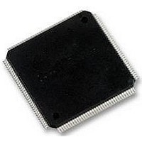
LCMXO2280C-5TN144C LATTICE SEMICONDUCTOR, LCMXO2280C-5TN144C Datasheet - Page 213

LCMXO2280C-5TN144C
Manufacturer Part Number
LCMXO2280C-5TN144C
Description
MACHXO PLD FLASH, SCRAM 1.8V, SMD
Manufacturer
LATTICE SEMICONDUCTOR
Series
MachXOr
Datasheet
1.LCMXO1200C-5TN144C.pdf
(244 pages)
Specifications of LCMXO2280C-5TN144C
Cpld Type
FLASH
No. Of Macrocells
1140
No. Of I/o's
113
Propagation Delay
3.6ns
Global Clock Setup Time
1.1ns
Frequency
600MHz
Supply Voltage Range
1.71V To 3.465V
Operating
RoHS Compliant
Available stocks
Company
Part Number
Manufacturer
Quantity
Price
Company:
Part Number:
LCMXO2280C-5TN144C
Manufacturer:
Lattice Semiconductor Corporation
Quantity:
10 000
Part Number:
LCMXO2280C-5TN144C
Manufacturer:
LATTICE/莱迪斯
Quantity:
20 000
- Current page: 213 of 244
- Download datasheet (9Mb)
Lattice Semiconductor
beginning of the design cycle. When the pipelining technique is applied, special care must be taken for the rest of
the design to account for the additional data path latency. The following illustrates the same data path before
(Figure 13-5) and after pipelining (Figure 13-6).
Figure 13-5. Before Pipelining
Figure 13-6. After Pipelining
Before pipelining, the clock speed is determined by the clock-to-out time of the source register, the logic delay
through four levels of combinatorial logic, the associated routing delays, and the setup time of the destination regis-
ter. After pipelining is applied, the clock speed is significantly improved by reducing the delay of four logic levels to
one logic level and the associated routing delays, even though the rest of the timing requirements remain the same.
It is recommended to check the Place and Route timing report to ensure that the pipelined design gives the desired
performance.
Comparing IF statement and CASE statement
CASE and IF-THEN-ELSE statements are common for sequential logic in HDL designs. The IF-THEN-ELSE state-
ment generally generates priority-encoded logic, whereas the CASE statement implements balanced logic. An IF-
THEN-ELSE statement can contain a set of different expressions while a Case statement is evaluated against a
common controlling expression. Both statements will give the same functional implementation if the decode condi-
tions are mutually exclusive, as shown in the following VHDL codes.
-- Case Statement — mutually exclusive conditions
process (s, x, y, z)
begin
end process;
O1 <= ‘0’;
O2 <= ‘0’;
O3 <= ‘0’;
case (s) is
end case;
FF1
when “00” => O1 <= x;
when “01” => O2 <= y;
when “10” => O3 <= z;
FF1
Function
Comb.
Function
Comb.
FF2
Slow Clock
Fast Clock
Function
Comb.
13-7
Function
Comb.
-- If-Then-Else — mutually exclusive conditions
process (s, x, y, z)
begin
end process;
O1 <= ‘0’;
O2 <= ‘0’;
O3 <= ‘0’;
if s = “00” then O1 <= x;
elsif s = “01” then O2 <= y;
elsif s = “10” then O3 <= z;
end if;
Function
Comb.
HDL Synthesis Coding Guidelines
for Lattice Semiconductor FPGAs
FF3
Function
FF1
Comb.
FF4
Related parts for LCMXO2280C-5TN144C
Image
Part Number
Description
Manufacturer
Datasheet
Request
R
Part Number:
Description:
IC, CPLD, FLASH, 2280 MACROCELL FTBGA256
Manufacturer:
LATTICE SEMICONDUCTOR
Part Number:
Description:
CPLD MachXO Family 1140 Macro Cells 1.8V/2.5V/3.3V 324-Pin FTBGA Tray
Manufacturer:
LATTICE SEMICONDUCTOR
Datasheet:

Part Number:
Description:
Microcontroller Modules & Accessories MACHXO CNRL EVB
Manufacturer:
Lattice
Datasheet:

Part Number:
Description:
IC, CPLD, FLASH, 2280 MACROCELL, TQFP144
Manufacturer:
LATTICE SEMICONDUCTOR

Part Number:
Description:
MACHXO PLD FLASH, SCRAM 1.8V, SMD
Manufacturer:
LATTICE SEMICONDUCTOR
Datasheet:
Part Number:
Description:
CPLD MachXO Family 1140 Macro Cells 1.8V/2.5V/3.3V 256-Pin FTBGA Tray
Manufacturer:
LATTICE SEMICONDUCTOR
Datasheet:
Part Number:
Description:
CPLD MachXO Family 1140 Macro Cells 1.8V/2.5V/3.3V 324-Pin FTBGA Tray
Manufacturer:
LATTICE SEMICONDUCTOR
Datasheet:
Part Number:
Description:
CPLD MachXO Family 1140 Macro Cells 1.8V/2.5V/3.3V 100-Pin TQFP Tray
Manufacturer:
LATTICE SEMICONDUCTOR
Datasheet:
Part Number:
Description:
ISPLSI2032-80LT44Lattice Semiconductor [In-System Programmable High Density PLD]
Manufacturer:
Lattice Semiconductor Corp.
Datasheet:
Part Number:
Description:
IC PROGRAMMED LATTICE GAL 16V8
Manufacturer:
Lattice Semiconductor Corp.
Datasheet:
Part Number:
Description:
357-036-542-201 CARDEDGE 36POS DL .156 BLK LOPRO
Manufacturer:
Lattice Semiconductor Corp.
Datasheet:
Part Number:
Description:
357-036-542-201 CARDEDGE 36POS DL .156 BLK LOPRO
Manufacturer:
Lattice Semiconductor Corp.
Datasheet:
Part Number:
Description:
357-036-542-201 CARDEDGE 36POS DL .156 BLK LOPRO
Manufacturer:
Lattice Semiconductor Corp.
Datasheet:
Part Number:
Description:
357-036-542-201 CARDEDGE 36POS DL .156 BLK LOPRO
Manufacturer:
Lattice Semiconductor Corp.
Datasheet:


