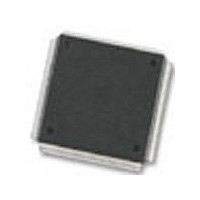
MC68376BAMFT20 Freescale Semiconductor, MC68376BAMFT20 Datasheet - Page 124

MC68376BAMFT20
Manufacturer Part Number
MC68376BAMFT20
Description
Manufacturer
Freescale Semiconductor
Datasheet
1.MC68376BAMFT20.pdf
(434 pages)
Specifications of MC68376BAMFT20
Cpu Family
68K/M683xx
Device Core
ColdFire
Device Core Size
32b
Frequency (max)
20MHz
Interface Type
QSPI/SCI
Program Memory Type
ROM
Program Memory Size
8KB
Total Internal Ram Size
7.5KB
# I/os (max)
18
Number Of Timers - General Purpose
2
Operating Supply Voltage (typ)
5V
Operating Supply Voltage (max)
5.25V
Operating Supply Voltage (min)
4.75V
On-chip Adc
16-chx10-bit
Instruction Set Architecture
RISC
Operating Temp Range
-40C to 125C
Operating Temperature Classification
Automotive
Mounting
Surface Mount
Pin Count
160
Package Type
PQFP
Lead Free Status / Rohs Status
Not Compliant
Available stocks
Company
Part Number
Manufacturer
Quantity
Price
Company:
Part Number:
MC68376BAMFT20
Manufacturer:
FREESCAL
Quantity:
245
- Current page: 124 of 434
- Download datasheet (7Mb)
5.7.5 Pin States During Reset
5.7.5.1 Reset States of SIM Pins
5-46
MOTOROLA
It is important to keep the distinction between pin function and pin electrical state clear.
Although control register values and mode select inputs determine pin function, a pin
driver can be active, inactive or in high-impedance state while reset occurs. During
power-on reset, pin state is subject to the constraints discussed in 5.7.7 Power-On
Reset.
Generally, while RESET is asserted, SIM pins either go to an inactive high-impedance
state or are driven to their inactive states. After RESET is released, mode selection
occurs and reset exception processing begins. Pins configured as inputs must be driv-
en to the desired active state. Pull-up or pull-down circuitry may be necessary. Pins
configured as outputs begin to function after RESET is released. Table 5-17 is a sum-
mary of SIM pin states during reset.
TouCAN (MC68376 only)
Pins that are not used should either be configured as outputs, or (if
configured as inputs) pulled to the appropriate inactive state. This
decreases additional I
supply level.
Module
CPU32
QADC
CTM4
QSM
TPU
Table 5-16 Module Pin Functions During Reset
SYSTEM INTEGRATION MODULE
PQA[4:3]/AN[56:55]/ETRIG[2:1]
PQB[3:0]/AN[z, y, x, w]/AN[3:0]
PQA[2:0]/AN[54:52]/MA[2:0]
DD
PQA[7:5]/AN[59:57]
PQB[7:4]/AN[51:48]
PQS[6:4]/PCS[3:1]
PQS3/PCS0/SS
CTD[10:9]/[4:3]
Pin Mnemonic
BKPT/DSCLK
TPUCH[15:0]
caused by digital inputs floating near mid-
DSI/IFETCH
PQS0/MISO
PQS1/MOSI
CPWM[8:5]
DSO/IPIPE
PQS2/SCK
PQS7/TXD
CANRX0
CANTX0
CTM4C
T2CLK
RXD
NOTE
TouCAN transmit
TouCAN receive
Discrete output
BKPT/DSCLK
Discrete input
Discrete input
Discrete input
Discrete input
Discrete input
Discrete input
Discrete input
Discrete input
Discrete input
Discrete input
Discrete input
Discrete input
Discrete input
DSI/IFETCH
TCR2 clock
DSO/IPIPE
TPU input
Function
RXD
USER’S MANUAL
MC68336/376
Related parts for MC68376BAMFT20
Image
Part Number
Description
Manufacturer
Datasheet
Request
R
Part Number:
Description:
Manufacturer:
Freescale Semiconductor, Inc
Datasheet:
Part Number:
Description:
Manufacturer:
Freescale Semiconductor, Inc
Datasheet:
Part Number:
Description:
Manufacturer:
Freescale Semiconductor, Inc
Datasheet:
Part Number:
Description:
Manufacturer:
Freescale Semiconductor, Inc
Datasheet:
Part Number:
Description:
Manufacturer:
Freescale Semiconductor, Inc
Datasheet:
Part Number:
Description:
Manufacturer:
Freescale Semiconductor, Inc
Datasheet:
Part Number:
Description:
Manufacturer:
Freescale Semiconductor, Inc
Datasheet:
Part Number:
Description:
Manufacturer:
Freescale Semiconductor, Inc
Datasheet:
Part Number:
Description:
Manufacturer:
Freescale Semiconductor, Inc
Datasheet:
Part Number:
Description:
Manufacturer:
Freescale Semiconductor, Inc
Datasheet:
Part Number:
Description:
Manufacturer:
Freescale Semiconductor, Inc
Datasheet:
Part Number:
Description:
Manufacturer:
Freescale Semiconductor, Inc
Datasheet:
Part Number:
Description:
Manufacturer:
Freescale Semiconductor, Inc
Datasheet:
Part Number:
Description:
Manufacturer:
Freescale Semiconductor, Inc
Datasheet:
Part Number:
Description:
Manufacturer:
Freescale Semiconductor, Inc
Datasheet:


