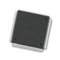
MC68376BAMFT20 Freescale Semiconductor, MC68376BAMFT20 Datasheet - Page 186

MC68376BAMFT20
Manufacturer Part Number
MC68376BAMFT20
Description
Manufacturer
Freescale Semiconductor
Datasheet
1.MC68376BAMFT20.pdf
(434 pages)
Specifications of MC68376BAMFT20
Cpu Family
68K/M683xx
Device Core
ColdFire
Device Core Size
32b
Frequency (max)
20MHz
Interface Type
QSPI/SCI
Program Memory Type
ROM
Program Memory Size
8KB
Total Internal Ram Size
7.5KB
# I/os (max)
18
Number Of Timers - General Purpose
2
Operating Supply Voltage (typ)
5V
Operating Supply Voltage (max)
5.25V
Operating Supply Voltage (min)
4.75V
On-chip Adc
16-chx10-bit
Instruction Set Architecture
RISC
Operating Temp Range
-40C to 125C
Operating Temperature Classification
Automotive
Mounting
Surface Mount
Pin Count
160
Package Type
PQFP
Lead Free Status / Rohs Status
Not Compliant
Available stocks
Company
Part Number
Manufacturer
Quantity
Price
Company:
Part Number:
MC68376BAMFT20
Manufacturer:
FREESCAL
Quantity:
245
- Current page: 186 of 434
- Download datasheet (7Mb)
8.4.1.1 Port A Analog Input Pins
8.4.1.2 Port A Digital Input/Output Pins
8.4.2 Port B Pin Functions
8.4.2.1 Port B Analog Input Pins
8.4.2.2 Port B Digital Input Pins
8-4
MOTOROLA
When used as analog inputs, the eight port A pins are referred to as AN[59:52]. Due
to the digital output drivers associated with port A, the analog characteristics of port A
are different from those of port B. All of the analog signal input pins may be used for
at least one other purpose.
Port A pins are referred to as PQA[7:0] when used as a bidirectional 8-bit digital input/
output port. These eight pins may be used for general-purpose digital input signals or
digital open drain pull-down output signals.
Port A pins are connected to a digital input synchronizer during reads and may be used
as general purpose digital inputs.
Each port A pin is configured as an input or output by programming the port data
direction register (DDRQA). Digital input signal states are read from the PORTQA data
register when DDRQA specifies that the pins are inputs. Digital data in PORTQA is
driven onto the port A pins when the corresponding bits in DDRQA specify outputs.
Refer to D.5.5 Port Data Direction Register for more information. Since the outputs
are open drain drivers (so as to minimize the effects to the analog function of the pins),
external pull-up resistors must be used when port A pins are used to drive another de-
vice.
The eight port B pins can be used as analog inputs, or as an 8-bit digital input only port.
Refer to the following paragraphs for more information.
When used as analog inputs, the eight port B pins are referred to as AN[51:48]/
AN[3:0]. Since port B functions as analog and digital input only, the analog character-
istics are different from those of port A. Refer to APPENDIX A ELECTRICAL CHAR-
ACTERISTICS for more information on analog signal characteristics. All of the analog
signal input pins may be used for at least one other purpose.
Port B pins are referred to as PQB[7:0] when used as an 8-bit digital input only port.
In addition to functioning as analog input pins, the port B pins are also connected to
the input of a synchronizer during reads and may be used as general-purpose digital
inputs.
Since port B pins are input only, there is no associated data direction register. Digital
input signal states are read from the PORTQB data register. Refer to D.5.5 Port Data
Direction Register for more information.
QUEUED ANALOG-TO-DIGITAL CONVERTER MODULE
USER’S MANUAL
MC68336/376
Related parts for MC68376BAMFT20
Image
Part Number
Description
Manufacturer
Datasheet
Request
R
Part Number:
Description:
Manufacturer:
Freescale Semiconductor, Inc
Datasheet:
Part Number:
Description:
Manufacturer:
Freescale Semiconductor, Inc
Datasheet:
Part Number:
Description:
Manufacturer:
Freescale Semiconductor, Inc
Datasheet:
Part Number:
Description:
Manufacturer:
Freescale Semiconductor, Inc
Datasheet:
Part Number:
Description:
Manufacturer:
Freescale Semiconductor, Inc
Datasheet:
Part Number:
Description:
Manufacturer:
Freescale Semiconductor, Inc
Datasheet:
Part Number:
Description:
Manufacturer:
Freescale Semiconductor, Inc
Datasheet:
Part Number:
Description:
Manufacturer:
Freescale Semiconductor, Inc
Datasheet:
Part Number:
Description:
Manufacturer:
Freescale Semiconductor, Inc
Datasheet:
Part Number:
Description:
Manufacturer:
Freescale Semiconductor, Inc
Datasheet:
Part Number:
Description:
Manufacturer:
Freescale Semiconductor, Inc
Datasheet:
Part Number:
Description:
Manufacturer:
Freescale Semiconductor, Inc
Datasheet:
Part Number:
Description:
Manufacturer:
Freescale Semiconductor, Inc
Datasheet:
Part Number:
Description:
Manufacturer:
Freescale Semiconductor, Inc
Datasheet:
Part Number:
Description:
Manufacturer:
Freescale Semiconductor, Inc
Datasheet:


