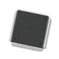
MC68376BAMFT20 Freescale Semiconductor, MC68376BAMFT20 Datasheet - Page 202

MC68376BAMFT20
Manufacturer Part Number
MC68376BAMFT20
Description
Manufacturer
Freescale Semiconductor
Datasheet
1.MC68376BAMFT20.pdf
(434 pages)
Specifications of MC68376BAMFT20
Cpu Family
68K/M683xx
Device Core
ColdFire
Device Core Size
32b
Frequency (max)
20MHz
Interface Type
QSPI/SCI
Program Memory Type
ROM
Program Memory Size
8KB
Total Internal Ram Size
7.5KB
# I/os (max)
18
Number Of Timers - General Purpose
2
Operating Supply Voltage (typ)
5V
Operating Supply Voltage (max)
5.25V
Operating Supply Voltage (min)
4.75V
On-chip Adc
16-chx10-bit
Instruction Set Architecture
RISC
Operating Temp Range
-40C to 125C
Operating Temperature Classification
Automotive
Mounting
Surface Mount
Pin Count
160
Package Type
PQFP
Lead Free Status / Rohs Status
Not Compliant
Available stocks
Company
Part Number
Manufacturer
Quantity
Price
Company:
Part Number:
MC68376BAMFT20
Manufacturer:
FREESCAL
Quantity:
245
- Current page: 202 of 434
- Download datasheet (7Mb)
8.12.3 Scan Modes
8.12.3.1 Disabled Mode and Reserved Mode
8.12.3.2 Single-Scan Modes
8-20
MOTOROLA
The QADC queuing mechanism provides several methods for automatically scanning
input channels. In single-scan mode, a single pass through a sequence of conversions
defined by a queue is performed. In continuous-scan mode, multiple passes through
a sequence of conversions defined by a queue are executed. The following para-
graphs describe the disabled/reserved, single-scan, and continuous-scan operations.
When the disabled mode or a reserved mode is selected, the queue is not active.
Trigger events cannot initiate queue execution. When both queue 1 and queue 2 are
disabled, no wait states will be inserted by the QADC for accesses to the CCW and
result word tables. When both queues are disabled, it is safe to change the QADC
clock prescaler values.
When application software requires execution of a single pass through a sequence of
conversions defined by a queue, a single-scan queue operating mode is selected.
In all single-scan queue operating modes, software must enable a queue for execution
by writing the single-scan enable bit to one in the queue’s control register. The single-
scan enable bits, SSE1 and SSE2, are provided for queue 1 and queue 2, respective-
ly.
Until the single-scan enable bit is set, any trigger events for that queue are ignored.
The single-scan enable bit may be set to one during the write cycle that selects the
single-scan queue operating mode. The single-scan enable bit can be written as a one
or a zero but is always read as a zero.
After the single-scan enable bit is set, a trigger event causes the QADC to begin exe-
cution with the first CCW in the queue. The single-scan enable bit remains set until the
queue scan is complete; the QADC then clears the single-scan enable bit to zero. If
the single-scan enable bit is written to one or zero before the queue scan is complete,
the queue is not affected. However, if software changes the queue operating mode,
the new queue operating mode and the value of the single-scan enable bit are recog-
nized immediately. The current conversion is aborted and the new queue operating
mode takes effect.
By properly programming the MQ1 field in QACR1 or the MQ2 field in QACR2, the fol-
lowing modes can be selected for queue 1 and/or 2:
• The pause bit is set in CCW0A and EOQ is programmed into CCW0A.
• During queue 1 operation, the pause bit is set in CCW20, which is also BQ2.
Do not use a reserved mode. Unspecified operations may result.
QUEUED ANALOG-TO-DIGITAL CONVERTER MODULE
NOTE
USER’S MANUAL
MC68336/376
Related parts for MC68376BAMFT20
Image
Part Number
Description
Manufacturer
Datasheet
Request
R
Part Number:
Description:
Manufacturer:
Freescale Semiconductor, Inc
Datasheet:
Part Number:
Description:
Manufacturer:
Freescale Semiconductor, Inc
Datasheet:
Part Number:
Description:
Manufacturer:
Freescale Semiconductor, Inc
Datasheet:
Part Number:
Description:
Manufacturer:
Freescale Semiconductor, Inc
Datasheet:
Part Number:
Description:
Manufacturer:
Freescale Semiconductor, Inc
Datasheet:
Part Number:
Description:
Manufacturer:
Freescale Semiconductor, Inc
Datasheet:
Part Number:
Description:
Manufacturer:
Freescale Semiconductor, Inc
Datasheet:
Part Number:
Description:
Manufacturer:
Freescale Semiconductor, Inc
Datasheet:
Part Number:
Description:
Manufacturer:
Freescale Semiconductor, Inc
Datasheet:
Part Number:
Description:
Manufacturer:
Freescale Semiconductor, Inc
Datasheet:
Part Number:
Description:
Manufacturer:
Freescale Semiconductor, Inc
Datasheet:
Part Number:
Description:
Manufacturer:
Freescale Semiconductor, Inc
Datasheet:
Part Number:
Description:
Manufacturer:
Freescale Semiconductor, Inc
Datasheet:
Part Number:
Description:
Manufacturer:
Freescale Semiconductor, Inc
Datasheet:
Part Number:
Description:
Manufacturer:
Freescale Semiconductor, Inc
Datasheet:


