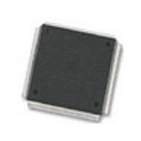
MC68376BAMFT20 Freescale Semiconductor, MC68376BAMFT20 Datasheet - Page 211

MC68376BAMFT20
Manufacturer Part Number
MC68376BAMFT20
Description
Manufacturer
Freescale Semiconductor
Datasheet
1.MC68376BAMFT20.pdf
(434 pages)
Specifications of MC68376BAMFT20
Cpu Family
68K/M683xx
Device Core
ColdFire
Device Core Size
32b
Frequency (max)
20MHz
Interface Type
QSPI/SCI
Program Memory Type
ROM
Program Memory Size
8KB
Total Internal Ram Size
7.5KB
# I/os (max)
18
Number Of Timers - General Purpose
2
Operating Supply Voltage (typ)
5V
Operating Supply Voltage (max)
5.25V
Operating Supply Voltage (min)
4.75V
On-chip Adc
16-chx10-bit
Instruction Set Architecture
RISC
Operating Temp Range
-40C to 125C
Operating Temperature Classification
Automotive
Mounting
Surface Mount
Pin Count
160
Package Type
PQFP
Lead Free Status / Rohs Status
Not Compliant
Available stocks
Company
Part Number
Manufacturer
Quantity
Price
Company:
Part Number:
MC68376BAMFT20
Manufacturer:
FREESCAL
Quantity:
245
- Current page: 211 of 434
- Download datasheet (7Mb)
MC68336/376
USER’S MANUAL
BQ2
00
39
P = PAUSE UNTIL NEXT TRIGGER
BYP = BYPASS
IST[1:0] = INPUT SAMPLE TIME
CHAN[5:0] = CHANNEL NUMBER AND END-OF-QUEUE CODE
The ten implemented bits of the CCW word can be read and written. Unimplemented
bits are read as zeros, and write operations have no effect. Each location in the CCW
table corresponds to a location in the result word table. When a conversion is complet-
ed for a CCW entry, the 10-bit result is written in the corresponding result word entry.
The beginning of queue 1 is the first location in the CCW table. The first location of
queue 2 is specified by the beginning of queue 2 pointer BQ2 in QACR2. To dedicate
the entire CCW table to queue 1, queue 2 is disabled, and BQ2 is programmed to any
value greater than 39. To dedicate the entire CCW table to queue 2, queue 1 is
disabled, and BQ2 is specified as the first location in the CCW table.
Figure 8-10 illustrates the operation of the queue structure.
9
P
CONVERSION COMMAND WORD
BYP
8
END OF QUEUE 1
END OF QUEUE 2
BEGIN QUEUE 1
BEGIN QUEUE 2
(CCW) TABLE
10-BIT CONVERSION COMMAND
7
IST[1:0]
6
WORD FORMAT
Figure 8-10 QADC Conversion Queue Operation
5
QUEUED ANALOG-TO-DIGITAL CONVERTER MODULE
4
CHAN[5:0]
3
2
SAMPLE, HOLD, AND
CHANNEL SELECT,
A/D CONVERSION
1
0
15
15
15
0
S
S = SIGN BIT
14
14
14
0
13
13
13
0
RIGHT JUSTIFIED, UNSIGNED RESULT
LEFT JUSTIFIED, UNSIGNED RESULT
12
12
12
0
LEFT JUSTIFIED, SIGNED RESULT
10-BIT RESULT, READABLE IN
11
11
11
RESULT
0
RESULT
THREE 16-BIT FORMATS
10
10
10
RESULT WORD TABLE
0
8
0
8
8
9
9
9
8
8
8
7
7
7
6
6
6
RESULT
5
5
0
5
0
4 3 2 1
4 3 2 1
0
4 3 2 1
0
0
0
MOTOROLA
0
0
0
0
0
0
0
0
0
QADC CQ
8-29
00
39
Related parts for MC68376BAMFT20
Image
Part Number
Description
Manufacturer
Datasheet
Request
R
Part Number:
Description:
Manufacturer:
Freescale Semiconductor, Inc
Datasheet:
Part Number:
Description:
Manufacturer:
Freescale Semiconductor, Inc
Datasheet:
Part Number:
Description:
Manufacturer:
Freescale Semiconductor, Inc
Datasheet:
Part Number:
Description:
Manufacturer:
Freescale Semiconductor, Inc
Datasheet:
Part Number:
Description:
Manufacturer:
Freescale Semiconductor, Inc
Datasheet:
Part Number:
Description:
Manufacturer:
Freescale Semiconductor, Inc
Datasheet:
Part Number:
Description:
Manufacturer:
Freescale Semiconductor, Inc
Datasheet:
Part Number:
Description:
Manufacturer:
Freescale Semiconductor, Inc
Datasheet:
Part Number:
Description:
Manufacturer:
Freescale Semiconductor, Inc
Datasheet:
Part Number:
Description:
Manufacturer:
Freescale Semiconductor, Inc
Datasheet:
Part Number:
Description:
Manufacturer:
Freescale Semiconductor, Inc
Datasheet:
Part Number:
Description:
Manufacturer:
Freescale Semiconductor, Inc
Datasheet:
Part Number:
Description:
Manufacturer:
Freescale Semiconductor, Inc
Datasheet:
Part Number:
Description:
Manufacturer:
Freescale Semiconductor, Inc
Datasheet:
Part Number:
Description:
Manufacturer:
Freescale Semiconductor, Inc
Datasheet:


